Omega Vehicle Security OMP-MODL Module Installation, Module Layer Requirements / Limitations

Models: OMP-MODL

1 297
Download 297 pages 51.3 Kb
Page 33
Image 33

3... INTERFACE MODULES

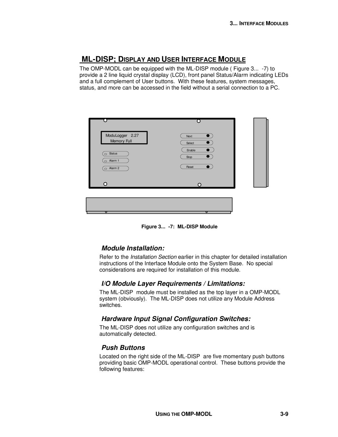
ML-DISP; DISPLAY AND USER INTERFACE MODULE

The OMP-MODL can be equipped with the ML-DISP module ( Figure 3... -7) to provide a 2 line liquid crystal display (LCD), front panel Status/Alarm indicating LEDs and a full complement of User buttons. With these features, system messages, status, and more can be accessed in the field without a serial connection to a PC.

ModuLogger 2.27

Memory Full

Status

Alarm 1

Alarm 2

Next

Select

Enable

Stop

Reset

Figure 3... -7: ML-DISP Module

Module Installation:

Refer to the Installation Section earlier in this chapter for detailed installation instructions of the Interface Module onto the System Base. No special considerations are required for installation of this module.

I/O Module Layer Requirements / Limitations:

The ML-DISP module must be installed as the top layer in a OMP-MODL system (obviously). The ML-DISP does not utilize any Module Address switches.

Hardware Input Signal Configuration Switches:

The ML-DISP does not utilize any configuration switches and is automatically detected.

Push Buttons

Located on the right side of the ML-DISP are five momentary push buttons providing basic OMP-MODL operational control. These buttons provide the following features:

USING THE OMP-MODL

3-9

Page 33
Image 33
Omega Vehicle Security OMP-MODL manual Module Installation, Module Layer Requirements / Limitations, Push Buttons