Version 5.0.1 January 2010 DOC2518C
Polycom RMX 2000/4000 Administrator’s Guide
Patent Pending
Regulatory Notices
RMX 2000 complies with IDA standards G0916-07
Table of Contents
Table of Contents
Iii
Entry Queues, Ad Hoc Conferences and SIP Factories
Address Book
Operator Assistance & Participant Move
Conference and Participant Monitoring
Vii
Viii
Call Flows 15-1
RMX Manager Application 16-1
RMX Administration and Utilities
17-56
ISDN/PSTN
Xii
Xiii
Ad Hoc Conferencing and External Database Authentication
Procedure 2 Configure the Modem
Connecting to the Alternate Management Network
Xiv
LPR
Setting Value
Entry Queue
Meeting Rooms
Standard Conferencing
Conferencing Modes
Supported resolutions
Supplemental Conferencing Features
To list Conference Profiles
Viewing Profiles
RMX Management pane, expand the Rarely Used list
Click the Conference Profiles button
Button Descriptions Name
Profile Toolbar
To define a new Profile
Defining Profiles
Field/Option Description
Click the Advanced tab
Define the following parameters
New Profile Advanced dialog box opens
At the End After Last Quits All the participants
At the End When Last Participant Remains
New Profile Video Quality dialog box opens
Click the Video Quality tab
People Video Definition
Guide, H.239 on
Content Video Definition
New Profile Video Settings dialog box opens
Click the Video Settings tab
YES
Is set to Flexible Mode
Number of Video Participants Auto Layout Default Settings
Number Available Video Layouts Video Windows
Conference Profiles
Select one of the Skin options
Field/Option Description
To modify the Profile Properties
Modifying an Existing Profile
Parameter Description
To delete a Conference Profile
Deleting a Conference Profile
Conference Profile is deleted
Video Session Modes
Dynamic Continuous Presence CP Mode
Continuous Presence CP Conferencing
High Definition Video Switching Mode
CIF
Video Resolutions in CP
2CIF/WCIF
Additional Intermediate Video Resolutions
Additional Video Resolutions in MPM+ Mode
352 x 288 pixels at 50 fps
512 x 288 pixels at 50 fps
Video Display with CIF, SD and HD Video Connections
Setting the Maximum CP Resolution for Conferencing
A 1X1 Video Layout
HD1080
CP Conferencing with H.263 4CIF
263 4CIF Guidelines
Guidelines
High Definition Video Switching
Modifying the HD Video Switching Threshold Bit Rate
Enabling HD Video Switching
Creating a High Definition Video Switching Profile
To Modify the HD Video Switching Threshold
Select the High Definition Video Switching check box
To Create an HD Enabled Profile
Monitoring High Definition Video Switching Conferences
239
Content Transmission Modes
Endpoint Capabilities
Content Protocol
Entry Queues
Defining Content Sharing Parameters for a Conference
Cascade Links
5H.239 Content Options
Guidelines for Sending Content to Legacy Endpoints
Sending Content to Legacy Endpoints
Interoperability with Polycom CMA and DMA
Content Display on Legacy Endpoints
Enabling the Send Content to Legacy Endpoints Option
To modify system flags
Legacyepcontentdefaultlayout
Layout Flag Value
Click OK Flag is updated in the Mcmsparameters list
Stopping a Content Session
To end the current Content session
Layout Flag Value
Enabling Lecture Mode
Lecture Mode
Enabling the Automatic Switching
To enable Lecture Mode for the Conference
Restricting Content Broadcast to Lecturer
Selecting the Conference Lecturer
When enabled, the following rules apply
Lecture Mode Monitoring
To control the Lecture Mode during an Ongoing Conference
Polycom RMX 2000/4000 Administrator’s Guide
Closed Captions
MPM and MPM+ Card Configuration Modes
Closed Captions Guidelines
Enabling Closed Captions
New Flag field enter Enableclosedcaption
To change the flag value
Media Encryption Guidelines
Media Encryption
Setting Permitted
Conference Access
Conference Participant
Encryption Connection
Entry Queue Access
YES
Move Guidelines
Encryption Flag Settings
To modify the Encryption flag
Enabling Encryption in the Profile
To enable encryption at the conference level
Enabling Encryption at the Participant Level
To enable encryption at the participant level
Monitoring the Encryption Status
Lost Packet Recovery
LPR Lost Packet Recovery
Packet Loss
Causes of Packet Loss
Enabling Lost Packet Recovery
Lost Packet Recovery Guidelines
Monitoring Lost Packet Recovery
Polycom RMX 2000/4000 Administrator’s Guide
RMX Telepresence Mode Guidelines
Telepresence Mode
System Level
Room Participant/Endpoint Level
Conference Level
TPX RPX
RPX and TPX Video Layouts
Number of Endpoints Layouts
2RPX and TPX Room System connected using RMX 2000/4000
Enabling Telepresence
Select the required video layout
To configure a participant/endpoint for Telepresence
Any conference that is ongoing can be saved as a template
Saving an Ongoing Conference as a Template
To save an ongoing conference as a template
RPX TPX
To start an ongoing conference from a Template
Starting an Ongoing Conference From a Template
3Cascaded Conferences Star Topology
Cascading Conferences Star Topology
4Video Layouts in Cascaded Conferences
Conference a Conference B
Creating the cascade-enabled Entry Queue
Creating the Cascade-enabled Entry Queue
Creating a cascade-enabled Dial-out link
To define a Cascade-Enabled Entry Queue
Additional Conferencing Information
To define the Dial-out Cascaded Link
Creating the Dial-out Cascaded Link
For Example 78485#24006#1234
Polycom RMX 2000/4000 Administrator’s Guide
To enable cascaded links to connect without a password
Enabling Cascaded Conferences without Password
Conference a Linked Conference
Monitoring Cascaded Conferences
Conference B Destination Conference
Additional Conferencing Information
MIH Cascading Levels
Cascading Conferences H.239-enabled MIH Topology
MIH Cascading allows
Master and Slave Conferences
MIH Cascading Guidelines
Conference B Conference C
Video Session Mode, Line Rate and Video Settings
Level
Content Sharing
Conf Kbps 128 256 384 512 768 1024 1472 1920 Mode
Setting up MIH Cascading Conferences
RMX to RMX Cascading
Dialing RMX 2000 Level Direction
Dialing RMX 2000 Level Direction
Creating a Cascade Enabled Entry Queue
Master RMX
Additional Conferencing Information
Creating the Cascaded Conferences
Creating a Cascade Enabled Dial-out Participant Link
To define the dial-out cascade participant link
17New Participant Dial-out Cascade Link
GatekeeperPrefix CascadeEnable
Additional Conferencing Information
MGC to
MGC to RMX 2000 Cascading
To MGC
Setting the flags in the MGC
Defining the Cascading Entry Queue in the MGC
Click OK If you changed the flags, reset the MCU
Participant Name
Participant Properties Identification dialog box, enter a
For Example 1002##12001##1234
For Example
H263ANNEXT=YES default
Setting the Flags on the RMX
FORCE1X1LAYOUTONCASCADEDLINK CONNECTION=YES default
Defining the Cascade Enabled Entry Queue on the RMX
Click OK Reset the MCU to apply the changes
For more details, see the RMX 2000 to RMX 2000 Cascading
Defining the Dial-out Participant on the RMX
Defining the Cascading Conferences
EQ ID
MCU Prefix as Password
Monitoring Participants in an MIH Cascaded Conference
Starting and Monitoring MIH Cascading Conferences
To monitor cascading enabled conferences
To view the linked Participant Properties
Viewing Participant Properties
Additional Conferencing Information
Meeting Rooms
Meeting Room Name Default Line Rate
To list Meeting Rooms
Meeting Rooms List
Meeting Rooms button
Meeting Rooms List is displayed
Meeting Room List columns include
Toolbar Right-click Description Button Menu
Meeting Room Toolbar & Right-click Menu
To create a new meeting room
Creating a New Meeting Room
Entry Queues
Entry Queues, Ad Hoc Conferences and SIP Factories
Parameter Value
Default Entry Queue properties
Polycom RMX 2000/4000 Administrator’s Guide
To define a new Entry Queue
Defining a New Entry Queue
RMX Management Rarely Used pane, click Entry Queues
Option Description
Option Description
ISDN/PSTN
Click OK New Entry Queue is added to the Entry Queues list
Listing Entry Queues
To view the list of Entry Queues
Modifying the EQ Properties
Setting a Transit Entry Queue
Transit Entry Queue
To modify the EQ
RMX Management Rarely Used pane click Entry Queues
To cancel the Transit Entry Queue setting
Ad Hoc Conferencing
Gateway to Polycom Distributed Media Application DMA
Creating SIP Factories
SIP Factories
To create a new SIP Factory
RMX Management Rarely Used pane, click SIP Factories
New Factory Properties
Click OK New SIP Factory is added to the list
Entry Queues, Ad Hoc Conferences and SIP Factories
Address Book
Displaying and Hiding the Address Book
Viewing the Address Book
Click the tab to re-open the Address Book
Adding a new participant to the Address Book Directly
Adding a Participant to the Address Book
To add a new participant to the Address Book
Ascii
Define the following fields
Only
SIP
Address, first select the type of alias and then enter
Field Description
SIP Only
IP Only
Define the following Advanced parameters
AGC
Cascaded Link If this participant is used as a link between
Click the Add to Address book button
Participant Properties window opens
Modifying Participants in the Address Book
When required, you can modify the participant’s properties
To modify participant properties in the Address Book
Participant’s Properties window appears
Searching the Address Book
Deleting Participants from the Address Book
To delete participants from the Address Book
To search for participants in the Address Book
To filter an address book field
Filtering the Address Book
To clear the filter and display all entries
Adding a New Group to the Address Book
Participant Groups
To define a New Group
To delete a Group
Deleting a Group from the Address Book
To Modify a Group
Modifying a Group in the Address Book
Exporting an Address Book
Importing and Exporting Address Books
To Export an Address Book
To Import and Address Book
Importing an Address Book
Integrating the Polycom CMA Address Book with the RMX
RMX Side On the RMX menu, click Setup System Configuration
CMA Address Book Integration Guidelines
System Flags Mcmsparametersuser dialog box opens
Content
Flag Description
External
Password External
Contentip
Http//IP address of the CMA server
User
Address Book
System
Guidelines
Resources
Reservations
Reservations
To open the Reservation Calendar
Using the Reservation Calendar
RMX Management pane, click the Reservations button
Toolbar Buttons
Reservations Views
Toolbar buttons functions are described in Table
Button Description
Day View
Week View
Today View
Single day is displayed
List View
To change between Week and Day views
Changing the Calendar View
To change to List View
To view Today the current date
Creating a New Reservation
Scheduling Conferences Using Reservation Calendar
To return to Calendar View
To create a new reservation
Method III To interactively define the duration
Open the Reservations
2New Reservation Reserved Resources
Click the Schedule tab
3New Reservation Schedule Tab
First, second,...,last Sun-Sat
Day 1-31 of every 1-12 months
Field Description
Click the Participants tab
Conference Template name Sales
Example
Display Name for single scheduled occurrence Sales
If 3 recurrences of the reservation are created
Reservations can be accessed and managed via all the views
Using the Week and Day views of the Reservations Calendar
Managing Reservations
Viewing and Modifying Reservations
To change the Reservation’s Start time
To move the Reservation to another time slot
To change the Reservation’s End time
To delete a single reservation
Deleting Reservations
Click the Delete Reservation button. or
To delete all recurrences of a reservation
Select Delete the series
Searching for Reservations using Quick Search
Click OK All occurrences of the Reservation are deleted
Reservations by Display Name
Clear the Quick Search field
To clear the search and display all reservations
Click Search
All Reservations are displayed
Operator Conferences
Operator Assistance & Participant Move
Operator Conference Guidelines
Defining the Components Enabling Operator Assistance
Click the Conference Chairperson tab
New Conference IVR Service Welcome dialog box opens
New Conference IVR Service General dialog box opens
Click the Conference Password tab
New Conference IVR Service Roll Call dialog box opens
Click the Video Services tab
Click the Operator Assistance tab
New Conference IVR Service Dtmf Codes dialog box opens
Polycom RMX 2000/4000 Administrator’s Guide
New Entry Queue IVR Service Conference ID dialog box opens
New Entry Queue IVR Service Welcome dialog box opens
New Entry Queue IVR Service Video Services dialog box opens
Defining a Conference Profile for an Operator Conference
1New Profile General Parameters
Line rate and use HD video
2New Profile Advanced Parameters
Recording link which is not considered a participant
3New Profile Video Quality Parameters
Content Settings
To start a conference from the Conference pane
Defining an Ongoing Operator Conference
4New Conference General Options
Be used in the Routing Name
Comma, colon and semicolon characters cannot
Field Description
New Conference Participants dialog box opens
To save an ongoing Operator conference as a template
Saving an Operator Conference to a Template
Right-click and select Save Conference to Template
Click the Start Conference from Template button. or
Starting an Operator Conference from a Template
Right-click and select Start Conference from Template
Requesting Help
Icon Status indication Description
Using Audible Alarms
Audible Alarms
Participant Alerts List
Move Guidelines
Moving Participants Between Conferences
Moving Participants
Using drag and drop
Moving a Participant Interactively
Operator Assistance & Participant Move
Conference Template
Guidelines
Conference Templates
Clicking the tab opens the Conference Templates list
Using Conference Templates
Conferences List toolbar includes the following button
Conference Template toolbar includes the following buttons
Creating a new Conference Template from Scratch
Creating a New Conference Template
To create a new Conference Template
Click the New Conference Template button
New Template Participants dialog box opens
Modify the fields of the General tab
New Participant General tab opens
New Participant Advanced tab opens
Optional. Click the Information tab
New Participant Information tab opens
New Conference Template Information tab opens
Saving an Ongoing Conference as a Template
Polycom RMX 2000/4000 Administrator’s Guide
Starting an Ongoing Conference From a Template
Starting an Operator Conference from a Template
Reservation
Scheduling a Reservation From a Conference Template
To schedule a Reservation from a Conference Template
Right-click and select Schedule Reservation from Template
Conference Template and Reservation Name
Series number 0000n of each reservation is appended to its
Deleting a Conference Template
Display Name
To delete Conference Templates
Conference and Participant Monitoring
General Monitoring
To view the parameters of an ongoing conference
Conference Level Monitoring
Following information appears in the General tab
Same line rate and use HD video
Conference Properties Advanced dialog box opens
Conference Properties Video Quality dialog box opens
Following information appears in the Advanced tab
Following information appears
Click the Video Settings tab to list the video parameters
Selecting a lecturer enables the Lecture Mode
Requesting Help
Icon Status indication Description
Participant Alerts List
Displaying Participants Properties
Participant Level Monitoring
Participant Properties Media Sources dialog box opens
IP Participant Properties
Field Description
Participant Status
Capabilities used for the connection
Columns
Channels
Maximum network jitter since the channel was
Field Description
Click the Gatekeeper Status tab to view its parameters
11Participant Properties Gatekeeper Status Parameters
Bit Rate
Monitoring ISDN/PSTN Participants
Audio
Algorithm
Participant Properties Media Sources dialog box is displayed
To view the participant’s properties during a conference
Field Description
14Participant Properties H.221 Parameters
Polycom RMX 2000/4000 Administrator’s Guide
15ISDN/PSTN Participant Properties Connection Status
16ISDN/PSTN Participant Properties Channel Status
MCU
Participant Phone Number In a dial-in
Defining the Recording Link
Configuring the RMX to enable Recording
10-1
Click OK Recording Link is added to the RMX unit
To define a Recording Link
10-2
Conference IVR Service Properties dialog box is displayed
Enabling the Recording Features in a Conference IVR Service
10-3
Enabling the Recording in the Conference Profile
To enable recording for a conference
10-4
10-5
Recording Link Encryption
Recording Link Encryption Guidelines
Recording Link Settings
See Enabling the Recording in the Conference Profile on
10-6
10-7
Profile Setting RSS Setting Flag Setting Recording Link
To manage the recording process using the right-click menu
Using the RMX Web Client to Manage the Recording Process
Managing the Recording Process
10-8
Name Description
10-9
10-10
Using Dtmf Codes to Manage the Recording Process
Monitoring the recording participant
Conference Recording with Codian IP VCR
10-11
10-12
11-1
Users, Connections and Notes
To view the users currently defined in the system
Listing Users
11-2
Adding a New User
Administrators can add new users to the system
11-3
11-4
Deleting a User
Click OK User’s password is changed
Changing a User’s Password
11-5
Disabling a User
To disable a user
11-6
Enabling a User
To enable a user
Renaming a User
To rename a user
11-8
Viewing the Connections List
Connections
To list the users who are currently connected to the MCU
11-9
Managing the user login process includes
User and Connection Management in Enhanced Security Mode
Managing RMX users includes
Controlling the user sessions includes
User Types
Managing the RMX Users
Disabling/Enabling Users
Renaming Users
Implementing Strong Passwords
Managing the User Login Process
Password Character Composition
11-12
Password Length
Implementing Password Re-Use / History Rules
11-13
Defining Password Change Frequency
Defining Password Aging
11-14
Temporary User Lockout
Forcing Password Change
User Lockout
11-15
User Lockout is an Audit Event
User Login Record
11-16
Controlling RMX User Sessions
Connection Timeout
Management Sessions per System
Sessions per User
Erase Session History After Logout
Session Timeout
11-18
To create a note
Using Notes
11-19
To delete a note
To open or edit a note
11-20
12-1
Network Services
Two IP Services are defined for the RMX
IP Network Services
Management Network Default IP Service Conferencing Service
Management Network Primary
To view or modify the Management Network Service
Default IP Service Conferencing Service
Modifying the Management Network
12-3
Modify the following fields
Management Network Properties IP dialog box opens
12-4
12-5
12-6
12-7
12-8
Click the Routers tab Modify the following fields
12-9
12-10
Click the DNS tab Modify the following fields
DNS
12-11
RMX 2000 only Click the LAN Ports tab
12-12
View or modify the following fields
Fast Configuration Wizard
Modifying the Default IP Network Service
To view or modify the Default IP Service
12-13
12-14
Default IP Service Networking IP dialog box opens
12-15
12-16
12-17
Click the Gatekeeper tab Modify the following fields
12-18
12-19
12-20
12-21
12-22
12-23
TOS
12-24
12-25
Click the SIP Servers tab Modify the following fields
Send Certificate
12-26
Username@domain name
12-27
12-28
Click the Security tab Modify the following fields
12-29
Ethernet Settings RMX 4000 Only
12-30
Modify the following field
2IP Network Services Properties RMX CS IP
To monitor signaling status
IP Network Monitoring
12-31
12-32
Click the H.323 tab H.323 tab displays the following fields
3IP Network Services Properties H.323
12-33
12-34
12-35
4IP Network Services Properties SIP Servers
IPv6 Guidelines
Default Management Network Service
RMX Internal Addresses
External Entities
12-37
Network Separation
Network Security
RMX
12-38
Enabling Network Separation
To enable Network Separation
12-39
12-40
Enter the Default Router IP Address
12-41
RMX Web Client Welcome screen is displayed
Click Login
12-42
Supported Capabilities and Conferencing Features
ISDN/PSTN Network Services
Non Supported Capabilities and Conferencing Features
12-43
Obtaining ISDN/PSTN required information
Adding/Modifying ISDN/PSTN Network Services
12-44
12-45
To Add an ISDN/PSTN Network Service
12-46
Click Next
12-47
12-48
12-49
Click Next Span Definition dialog box is displayed
12-50
12-51
Click Save & Continue
12-52
Move the slider to the required setting
Modifying an ISDN/PSTN Network Service
To Modify an ISDN/PSTN Network Service
Click Save & Close
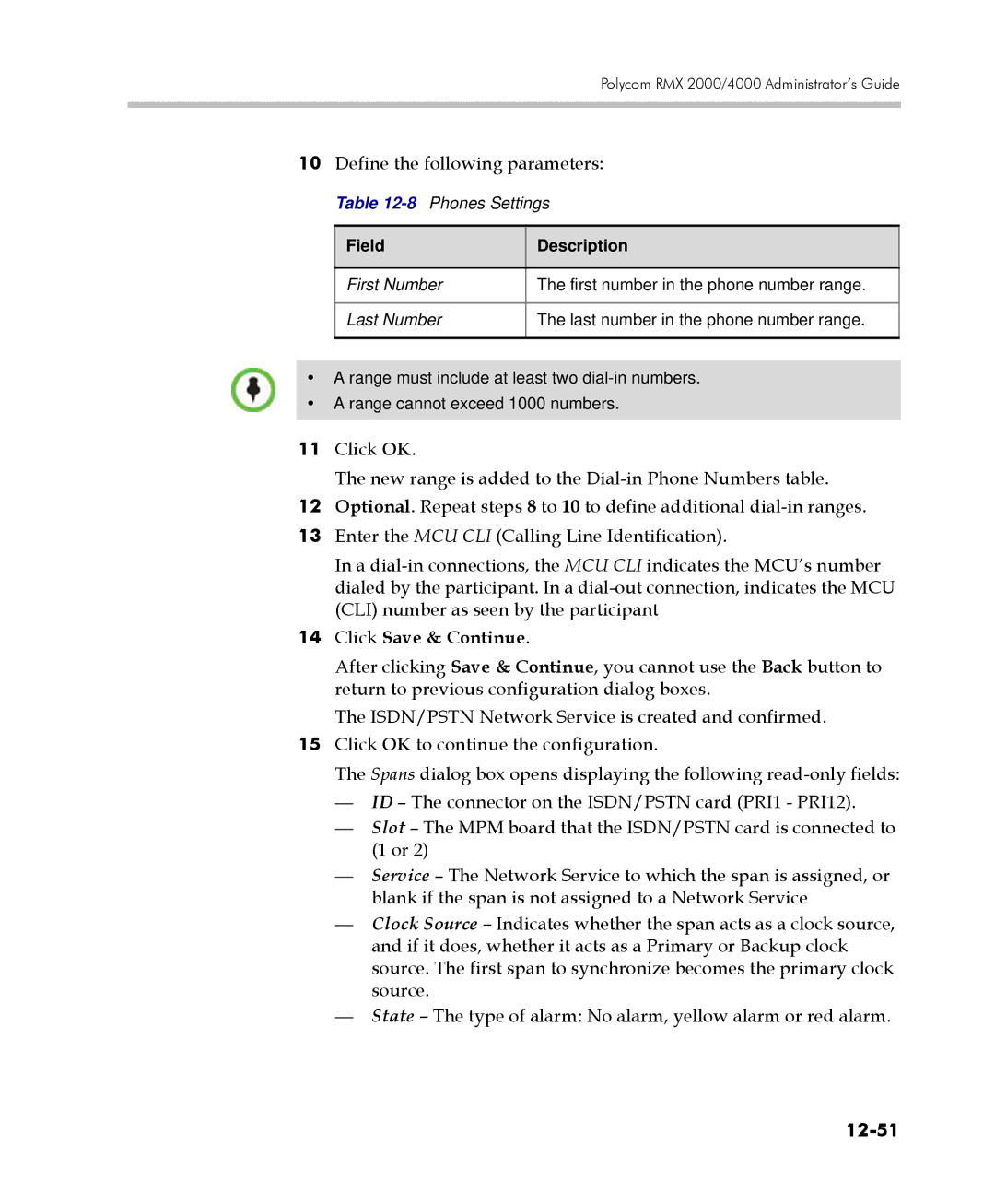
Phones
Span Definition
Spans
12-54
12-55
12-56
13-1
IVR Services
To view the IVR Services list
IVR Services List
13-2
13-3
IVR Services Toolbar
Button Button Name Descriptions
Adding Languages
Conference IVR Services list, click the Add Supported
To add a language
Languages button
13-5
To upload messages to the MCU
Message Message Type Category
13-6
13-7
13-8
Defining a New Conference IVR Service
Defining a New Conference IVR Service
To define a new Conference IVR Service
13-9
IVR
13-10
13-11
13-12
13-13
13-14
13-15
Message Type Description
13-16
13-17
13-18
13-19
Roll Call Record
13-20
Roll Call Description Message
13-21
Ivrrollcallusetonesinsteadof
13-22
Video Description Services
13-23
Operation Dtmf String Permission
13-24
13-25
13-26
Defining a New Entry Queue IVR Service
Entry Queues IVR Service
To set up a new Entry Queue IVR Service
New Entry Queue IVR Service Global dialog box opens
13-28
13-29
13-30
Select the voice messages
13-31
IVR Service button
To select the default Conference IVR Service
To select the Default Entry Queue IVR Service
13-32
To modify the properties of an IVR Service
Service
13-33
Replacing the Music File
Install Music File window opens
Adding a Music File
To replace the Music file
13-35
Creating Audio Prompts and Video Slides
To define the format settings for audio messages
Recording an Audio Message
13-36
13-37
Attributes list, select 16.000 kHz, 16Bit, Mono
13-38
To record a new audio message
13-39
To record additional messages, repeat steps 1 to
Creating a Welcome Video Slide
To create a welcome video slide
13-40
13-41
Default IVR Prompts and Messages
Message Type Message Text File Name
13-42
13-43
NID
13-44
To control the volume of IVR music, messages and Roll Call
Volume Control of IVR Messages, Music and Roll Call
Ivrmusicvolume
Ivrmessagevolume
13-46
Ivrrollcallvolume
14-1
Call Detail Record CDR Utility
CDR File Formats
CDR File
14-2
CDR File Contents
14-4
Viewing the Conference Records
Viewing, Retrieving and Archiving Conference Information
To open the CDR utility
14-5
To refresh the CDR list
Refreshing the CDR List
14-6
To retrieve and archive CDR records
Retrieving and Archiving Conference CDR Records
14-7
Menu Option Button Action
14-8
Direct Dialing
Call Flows
15-1
15-2
Dialing from H.323 Endpoints
15-3
Dialing string
15-4
Dialing from SIP Endpoints
Optional
Gateway IVR
15-5
15-6
Dialing from ISDN/PSTN Endpoints
15-7
MCU prefix in Gkgw Profile ID
15-8
Interoperability with CMA
15-9
Connection Indications
15-10
Gateway Functionality
15-11
Defining the IVR Service for Gateway Calls
Configuring the Gateway Components on the RMX
To define a new Conference IVR Service for gateway calls
15-12
15-13
15-14
15-15
To define a Conference Profile for Gateway Sessions
Defining the Conference Profile for Gateway Calls
15-16
Defining the Gateway Profile
Define the required settings for Encryption and LPR
To define a new Gateway Profile
RMX Management Rarely Used pane, click Gateway Profiles
15-18
15-19
15-20
Click OK New Gateway Profile is added to the list
Displaying the Connection Information System Configuration
15-21
Gateway Session Parameters
Monitoring Ongoing Gateway Sessions
15-22
15-23
Connected Participant Parameters
15-24
Dialing to Polycom DMA
15-25
To set up the Meeting Room for direct dialing
15-26
16-1
Installing the RMX Manager
16-2
Click the Install RMX Manager link
16-3
16-4
To use the browser
Starting the RMX Manager Application
To use the Windows Start menu Click Start Programs
Click All Programs Polycom RMX Manager
16-6
Connecting to the MCU
16-7
To connect the RMX Manager to an MCU
16-8
16-9
RMX Manager Main Screen
16-10
MCUs Pane
MCUs Toolbar
Conferences Pane
MCUs toolbar contains the following buttons
16-11
Conferences list toolbar contains the following buttons
RMX Management
Monitoring conferences
Starting a new conference
Status Bar
List Pane
System Alerts
16-13
Participant Alerts
Address Book
Port Usage Gauges
MCU State
Conference Templates
Adding MCUs to the MCUs List
To add an RMX unit
16-15
MCU IP
16-16
443
FieldDescription
16-17
Starting a Conference
Administrator’s Guide, Meeting Rooms on
Starting a Conference from the Conferences Pane
Start a Reservation
16-19
New Conference General dialog box opens
To start a conference from the Reservation Calendar
Starting a Reservation
Reservation Calendar is displayed
Click the New Reservation button
16-21
16-22
Monitoring Conferences
16-23
Grouping the Participants by MCU
16-24
Start Monitoring/Stop Monitoring
To view and/or modify the MCU Properties
Modifying the MCU Properties
16-25
Removing an MCU from the MCUs Pane
Disconnecting an MCU
To disconnect an MCU
To Remove an MCU from the list
MCU icon is removed from the MCUs pane
Changing the RMX Manager Language
To select a language
16-27
To install the RMX Manager
Installing RMX Manager for Secure Communication Mode
RMX Management pane, click IP Network Services
16-28
Click OK Click the DNS tab
Clear the Secured RMX Communication check box
Enter the Local Domain Name
16-29
16-30
Create a Certificate Request
16-31
Set the RMX to Secure Communication Mode
16-32
16-33
Using an Internal Certificate Authority
Select Base-64 encoded X.509 .CER
Certificate Export Wizard is displayed
16-34
16-35
16-36
Successful export message is displayed Click the OK button
17-1
System and Participant Alerts
To view the System Alerts list
System Alerts
17-2
17-3
To view the Participants Alerts list
Participant Alerts
17-4
Modifying System Flags
System Configuration
17-5
17-6
Mcmsparameters tab, the following flags can be modified
17-7
17-8
Externaldblogin
Version 4.x and earlier enter the IP
Externaldb
17-9
17-10
17-11
17-12
17-13
17-14
17-15
17-16
To add a flag
Manually Adding and Deleting System Flags
17-17
17-18
Following flags can be manually added to
Flag and Value Description
17-19
17-20
17-21
17-22
17-23
17-24
17-25
17-26
17-27
17-28
To delete a flag
Sendwideresto
17-29
Legacyepcontentdefaultlayout Flag Values
17-30
Jitcmode System Flag
Range Default Network Security
17-31
Flag
Windowin Minutes Lastlogin YES Attempts User
Alive Timeout Session
17-32
Timoutin Minutes Userlockout YES
Force YES YES/NO Strong Password Policy Minpassword
Range Default Password Management
17-33
Customizing the Default Auto Layout
Auto Layout Configuration
Default Auto Layout is controlled by 11 flags
17-34
17-35
Default Value Possible Values
CPLAYOUT1X1 CPLAYOUT1X2 CPLAYOUT1X2HOR
CPLAYOUT1X2VER
17-36
Predefined
17-37
AUTOLAYOUT5
Altering the clock
RMX Time
To Alter the RMX Time
17-38
17-39
Resource Capacity
Resource Management
17-40
17-41
Resource Capacity Modes
Resource Usage
Resolution/fps Video Resources Used
Continuous Presence
17-42
WCIF/25 WSIF/30
17-43
WVGA/30 WVGA/25
Voice
High Definition Video Switching
17-44
WSIF/60 WCIF/60
Flexible Resource Capacity Mode
Video/Voice Port Configuration
Fixed Resource Capacity
17-45
17-46
Configuring the Video/Voice Resources in MPM Mode
To allocate Audio Only ports in MPM+ mode
Configuring the Video/Voice Resources in MPM+ Mode
RMX menu, click Setup Video/Voice Port Configuration
Flexible Resource Capacity
17-48
To allocate resources in Fixed Resource Capacity mode
Audio Only
Resource Type Maximum
17-49
17-50
17-51
Forcing Video Resource Allocation to CIF Resolution
To force CIF resource
To cancel the forcing of CIF resource
17-52
Resource Report
Main toolbar, click Administration Resource Report
Displaying the Resource Report
17-53
Example An RMX 2000 in Flexible Resource Capacity Mode has
Resource Report Display in Flexible Resource Capacity Mode
17-54
Column Description
Port Gauges
Resource Report is displayed as follows
17-55
Example An RMX 2000 in Fixed Resource Capacity Mode has
Resource Report in Fixed Resource Capacity Mode
17-56
17-57
ISDN/PSTN
Port Usage
Setting the Port Usage Threshold
To Set the Port Usage Threshold
17-58
17-59
SIP Dial-in Busy Notification
17-60
Port Usage Gauges
Audio Ports Gauge
Port Gauges in Flexible/Fixed Capacity Modes
Video Ports Gauge
17-61
To view the System Information properties box
System Information
17-62
RMX
17-63
17-64
Detailed Description
Snmp Simple Network Management Protocol
MIB Management Information Base Files
Private Mibs
Support for MIB-II Sections
Alarm-MIB
MIB H.341 H.323
Standard MIBs
320MCU-MIB
17-67
17-68
Traps
17-69
Status Trap Content
Defining the Snmp Parameters in the RMX
To enable Snmp option
17-70
17-71
RMX-SNMP Properties Traps dialog box opens
Click the Traps tab
17-72
17-73
17-74
RMX-SNMP Properties Security dialog box opens
RMX Snmp Properties Security dialog box, click OK
Accepted Host IP Address dialog box opens
17-75
Using Audible Alarms
Audible Alarms
Audible Alarm Permissions
17-76
When selected all audible alarms are immediately stopped
Configuring the Audible Alarms
Stop Repeating Message
User Customization
17-78
User Customization window opens
Download Audible Alarm File window opens
Replacing the Audible Alarm File
17-79
17-80
Customizing the Multilingual Setting
Multilingual Setting
To customize the Multilingual Setting
17-81
Banner Display and Customization
Banners Configuration dialog box opens
Customizing Banners
17-82
Banner Display
Login Screen Banner
Customize the banners by modifying the following fields
17-83
17-84
17-85
Main Screen Banner
Software Management
Backup and Restore Guidelines
17-86
Backup Configuration dialog box opens
Using Software Management
Browse to the Backup Directory Path and then click Backup
17-87
17-88
Browse to the Install Path and then click Install
Ping RMX
Using Ping
To Ping a network entity from the RMX
17-89
17-90
Modify or complete the following fields
To configure the notifications
Notification Settings
17-91
17-92
Following notification options are displayed
17-93
Logger Diagnostic Files
File name structure
Following tasks can be performed
File name format
Retrieving the Logger Files
Viewing the Logger File contents
Auditor Files
Auditor
Auditor Event History File Storage
17-96
Auditor Files dialog box is displayed
Retrieving Auditor Files
17-97
Click Retrieve Files
To retrieve files for storage on a workstation
To open the file in the Auditor File Viewer
17-98
Auditor File Viewer is displayed
Auditor File Viewer
17-99
17-100
Following fields are displayed for each event
GET Http
17-101
PUT Http
Mkdir Http
Lists Alerts and Faults that are recorded by the Auditor
Alerts and Faults
Audit Events
To open an auditor event file stored on the workstation
17-103
Lists Transactions that are recorded by the Auditor
Transactions
17-104
17-105
ActiveX Bypass
Installing ActiveX
17-106
17-107
To reset the RMX
Resetting the RMX
17-108
17-109
18-1
Viewing the Status of the Hardware Components
18-2
18-3
HW Monitor Pane Toolbar
Button Name Description
Hardware Properties dialog box has the following structure
Viewing Hardware RMX 2000 Component’s Properties
18-4
18-5
To view the MCU Properties
18-6
18-7
18-8
To view the Card Properties
18-9
Backplane Properties
To View the Supporting Hardware Components Properties
18-10
FAN Properties
Field Description General Settings
18-11
Fans
18-12
LAN 0, LAN 1, LAN 2 Properties
18-13
Viewing Hardware RMX 4000 Component’s Properties
18-14
18-15
18-16
18-17
18-18
18-19
Backplane+ Properties
18-20
18-21
18-22
Diagnostic Mode
To run Diagnostics on a Hardware Component
Performing Diagnostics
18-23
18-24
18-25
Click the Run Selected Tests button
MCU Monitor
Diagnostics Monitoring
18-26
18-27
Cards Monitor
18-28
Error Buffer
IP Disconnection Causes
Appendix a
Appendix A-Disconnection Causes
Disconnection Cause Description
Not wish to take the call at this time
Disconnection Cause Description
Returned
Disconnection Cause Description
Disconnection Cause Description
Disconnection Cause Description
Disconnection Cause Number Summary Description
Isdn Disconnection Causes
Disconnection Cause Number Summary Description
Enquiry
Status
CUG
Number Summary Description
Disconnection Cause
Suspended a Resume message cannot be executed by
100
Message with
Appendix A-Disconnection Causes
Appendix B
Alarms
Alarm Code Alarm Description
CPU slot ID not identified
Encryption Server Error. Failed to
Alarm Code Alarm Description
Free space percentage% free space Blocks
Alarm Code Alarm Description
GUI System configuration file is invalid
Alarm Code Alarm Description
Alarm Code Alarm Description
Polycom RMX 2000/4000 Administrator’s Guide
Produce a Redalarm Alert
Adding the appropriate flag is the system configuration
DNS
System has been configured for Jitc
User Name Support cannot be used
Appendix C
Appendix C-CDR Fields Unformatted File
Conference Summary Record
Field Description
Standard Event Record Fields
Event Records
Event Types
Event Code Event Name Description
NEW
23 H323 Participant Connected
Undefined
Billing Code
Recording
SIP
Link
SIP Private
Terminate
Party Continue IPV6 Address
User ADD
User Delete
Reconnect
User Update
User SET END
Time
Operator Move Party from
Attend Party
Back to
Continue
Update Participant Continue
Continue 1, User Update
Participant Disconnected
2101, 2105 Defined Participant
Table C-35, Event Fields for Event
On page C-22
Conference Start Continue
Event Specific Fields
Polycom RMX 2000/4000 Administrator’s Guide
Field Description
Time the conference starts, without any participant
Maximum number of participants that can connect to
Automatic switching between participants is enabled
Table C-6
Any other number Unknown
NTI TIE Trunk
NTI FX
ATT Accunet
Field Description
Table C-10Event fields for Event 4 ISDN/PSTN Channel
Field Description
Field Description
Field Description
User Update Participant
Field Description
A dial-out connection, participant phone numbers are
323
Tel URL
SIP URI
User Update Participant Continue
Table C-17Event fields for Event 15 H323 Call Setup
Field Description
Field Description
Field Description
SIP
MCU
SIP URI
Name sent by the end point
Table C-23Event Fields for Event 22 Dtmf Code Failure
Verified by authentication
Table C-28
Polycom RMX 2000/4000 Administrator’s Guide
Destination Conf
Field Description
MCU
Isdn
Terminal
SIP URI
VIP
Table C-35
Value Call Disconnection Cause
Disconnection Cause Values
191 H323 call close. Remote busy
Value Call Disconnection Cause
Value Call Disconnection Cause
Following MGC Manager events are not supported by the RMX
MGC Manager Events that are not Supported by the RMX
Appendix C-CDR Fields Unformatted File
Appendix D
Ad Hoc Conferencing without Authentication
Starting a conference uses the following method
Ad Hoc Conferencing without Authentication
Ad Hoc Conferencing with Authentication
Network
Polycom RMX 2000/4000 Administrator’s Guide
Conference Access with External Database Authentication
Network
Conference Access Validation All Participants Always
Page
Network
Conference Access Validation Chairperson Only Upon Request
Page
Authentication Settings
Ad Hoc Settings
External Database Application Settings
Flag Description and Value
To set the System Configuration flags
Externaldb
Set the External Server Authentication field to Numeric ID
Set the External Server Authentication field to
Enabling External Database Validation for Conferences Access
Appendix E
Field Description
Number of packets arriving out of order. The fol
Out of Order
Field Description
Purchasing a Certificate
Switching to Secure Mode
Table F-1Create Certificate Request
To install the certificate
Installing the Certificate
Click Send Details
Appendix F-Secure Communication Mode
When Secure Communications Mode is enabled
Enabling Secure Communication Mode
Creating/Modifying System Flags
Securityprotocol
Alternate Management Network
Securing an External Database
Appendix F-Secure Communication Mode
Alternate Management Network
Management Network Primary
Logged in on the Management Network
Configuring the Workstation
Separation on
To modify the workstation’s IP addresses
Polycom RMX 2000/4000 Administrator’s Guide
Appendix G-Configuring Direct Connections to RMX
Example IP address near 192.168.1.nn
IP Address
To connect directly to the RMX
Connecting to the Management Network
Appendix G-Configuring Direct Connections to RMX
To connect to the Alternate Management Network
Connecting to the Alternate Management Network
Procedure 1 Install the RMX Manager
Connecting to the RMX via Modem
Procedure 2 Configure the Modem
Configure the modem as follows
To create a dial-up connection
Procedure 3 Create a Dial-up Connection
Appendix G-Configuring Direct Connections to RMX
Polycom RMX 2000/4000 Administrator’s Guide
Appendix G-Configuring Direct Connections to RMX
Polycom RMX 2000/4000 Administrator’s Guide
To Connect using the RMX Manager To use the browser
Procedure 4 Connect to the RMX
To use the Windows Start menu
Click All Programs
Appendix H
Setting the Trusted Host and Static Route for RMX
Configuring the OCS for RMX 2000/4000
To set the RMX as trusted and define Static Routes in OCS
Open the OCS Management application
Pool Front End Properties dialog box opens
Expand the Enterprise Pools list
Click the Host Authorization tab
To add RMX to the Routing Roles
Page
To create the TLS certificate in the OCS
Available Certificate Tasks window appears
Delayed or Immediate Request window appears
Select Create a New Certificate and click Next
Select the Mark cert as exportable check box
Name and Security Settings window appears
Organization Information window appears
Your Server’s Subject Name window appears
Choose a Certification Authority window appears
Geographical Information window appears
Certificate Wizard Completed window appears MS R2
Assign Certificate Task window appears
Click Finish MS R2
Available Certificates window appears
Select Export a certificate to a *.pfx file and click Next
Export Certificate Password window appears
Certificate Wizard Completed window appears
To create the certPassword.txt file
Load Front End Properties dialog box opens
Page
Service
DNS Servers Addresses
To configure the RMX IP Network Service
Defining a SIP Network Service in the RMX
Page
Polycom RMX 2000/4000 Administrator’s Guide
Page
Default IP Service Networking IP dialog box, click OK
Polycom RMX System Flag Configuration
Sipfreevideoresources
Flag Name Value and Description
ENV
Sipfastupdateinterval
To dial in directly to a conference or Entry Queue
Dialing to an Entry Queue, Meeting Room or Conference
Enter the conferencing entity SIP URI in the format
Conferencing entity routing name@domain name
Active Alarms
Active Alarms and Troubleshooting
OCS
Known Issues
Troubleshooting