Merlin
1990 AT&T Issue All Rights Reserved January
System Hardware
System Description
Whats in This Manual
System Overview
System Overview
Merlin II system configuration System Overview
Data feature
Size, type, and features of a Merlin II system are
Determined using system planning forms
For administration purposes
System Overview
A Merlin II system behind-switch operation System Overview
System Overview
System Overview
System Overview
Merlin II Attendant operation System Overview
FM1
FM1 FM2
FM2
FM1 FM2
FM1 FM2
FM1 FM2
FM1 FM2
System Hardware
Control unit components
Control unit components System Hardware
System Hardware
System Hardware
Module controls and indicators
Module controls and indicators
Green = test condition Amber = busy Red = standby mode
System Hardware
System Hardware
A selection of analog voice terminals System Hardware
Basic Operation of Voice Terminals
System Hardware
Calls
Accessories described here
Alerter Accessories. Devices such as a horn, bell
Alert Adapter so that people working in noisy or
A selection of Merlin II system accessories System Hardware
Basic Telephone and Modem Interface 2 BTMI-2
System Hardware
System Hardware
Theory of Operation
System architecture Theory of Operation
Theory of Operation
Theory of Operation
Analog to Digital Signal Processing
PCM uses PAM as its starting point but goes further
Mu-Law
150 …
External paging interface
Module slots Board signatures Time slots 256
108
Music-on-Hold interface
Signaling
11 E&M signaling Tie Line Parameters
Theory of Operation
Theory of Operation
Local
20 to 4800 ms increments of 20 ms Ms default
140 to 2400 ms increments of 10 ms
Same Site Simplex System Or Inter Type Building
Signaling Protected
Mode Location
Type
Standard Unit Network
Far End
Merlin II System
Other Inter Protected Requires a Building Type Protection
System Connectivity
System Connectivity
Merlin II System Control unit
Modem Pools
Merlin II System
Merlin II System control unit
D8W cord Modem pool
General Requirements for Modems
System Connectivity
MUSIC-ON-HOLD External Loudspeaker Paging
4PT 5PR
System Connectivity
Preinstallation Requirements
Installation
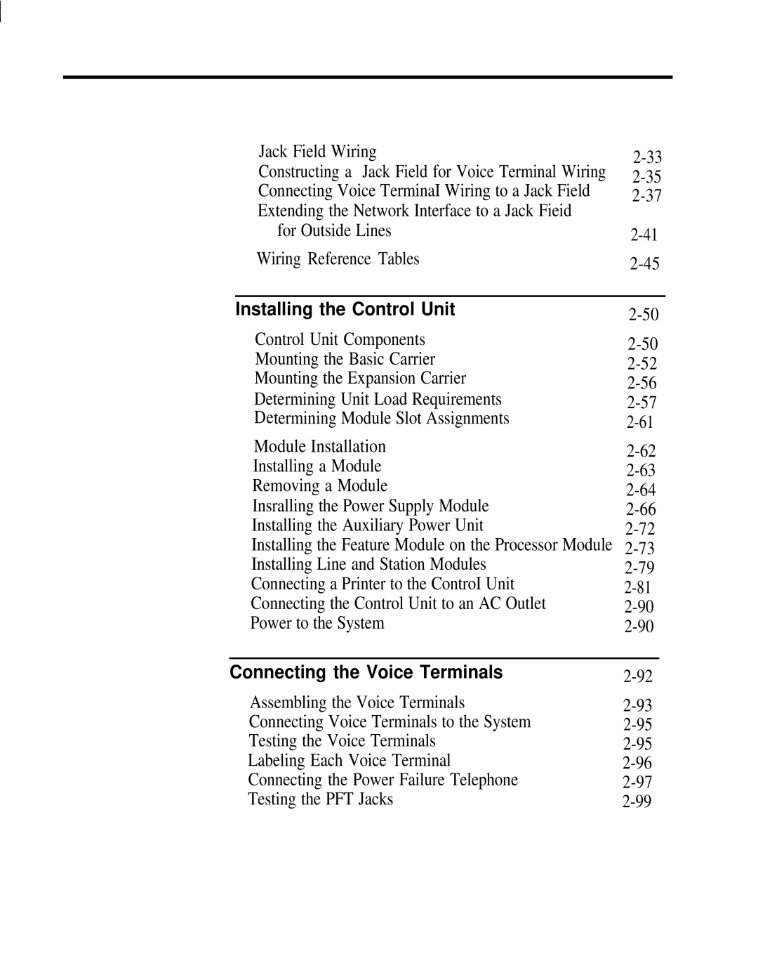
Installing the Control Unit
Modifying the System
Preinstallation Requirements
Without dc voltages being affected
Specification for an ac line voltage low of 99 VAC
Other splices, and should meet these specifications
Max. current amperes per power supply
Max. power use watts per power supply
Installed at the control unit location, additional
Mounting surface Hardware required
System Grounding Requirements
Merlin II System control unit Central Office
Check the ac outlet for proper ground with a circuit tester
CO Line Protector Surge Protectors
Static Discharge Problems
Solutions to Radio- Frequency Interference Problems
System Grounding Requirements
Typical Merlin II System Wiring
Wiring the System
Merlin II System control unit
Function as follows
Are for basic telephones only. In case of a power
There are various types of jacks on the line and station
Modules -3.Each type of jack has a specific
Line and station module jacks Wiring the System
012
Outside Line Wiring
Network interface adapters Wiring the System
Testing the Outside Lines
To number all the line jacks on the modules themselves
Wiring the System
Tie Line Module wiring Wiring the System
Voice Terminal Wiring
Pair modular jumper cords. These cords are for
Connecting Voice Terminal Wiring Directly
Wiring the System
Wiring a Voice Terminal for TWO VOICE-PAIRS
PFT
O O O O O O R T R T R T
Standard 4-PAIR Wiring
Brand Rex BR866-JC
Wiring the System
Jack Field Wiring
Wiring the System
Constructing a Jack Field for Voice Terminal Wiring
Wiring the System
Topics
Shop
Wiring the System
Wiring the System
Wiring the System
Wiring the System
Labeling Jacks and Boxes
Wiring the System
62400 Net Intf Adptr 267C Adapter
2A Adapter Mounting
Z601A Adapter
Z610A Adapter
Black GND Yellow V2T Brown V2R Slate BR-W
48V
Green RED Black
CO Line Wiring
From Merlin
10and are listed below
Basic Carrier Assembly
Feature Module
Required components of a Merlin
Installing the Control Unit
Mounting the Basic Carrier
Mounting surface 18Backboard
Installing the Control Unit
12 Mounting the basic carrier Installing the Control Unit
When the carriers are completely engaged, tighten the screws
Determining Unit Load Requirements
Installing the Control Unit
BIS-10 voice terminal
2x9
Button 1x8 Button Hfai 1X5 Digital 1X4
Install modules on the carrier from left to right
Power Supply Module in the leftmost slot
Processor Module before installing
Leftmost slot must contain the Power Supply Module
Module Installation
Installing a Module
Removing a Module
Page
Installing the Power Supply Module
Installing a Frequency Generator Power Supply Module
Installing the Control Unit
Transformer
Installing the Control Unit
Installing the Control Unit
Installing the Auxiliary Power Unit
19 Connecting the Auxiliary Power Unit to the control unit
Installing the Control Unit
Feature module Processor module
Installing the Control Unit
Bottom header AA Do not touch
Modifying the 517B7 Processor Module for Square Key
Line 400 with Dtmf Module Line 800 Module
Installing a Tie Line Module
If you are installing a Basic Telephone Module, you also
Installing the Control Unit
D R port Modular Z200A R d
1200
LQ or NLQ
144
B1-DIR.1
DIP1-Open DIP2-Closed DIP2-Open DIP3-Open DIP4-Open
Installing the Control Unit
Installing the Control Unit
Installing the Control Unit
ADU
Power to the System
To Turn the Power Off Normal Operation
Connecting the Voice Terminals
Assembling the Voice Terminals
Page
Back to the center position
Slide the T/P switch to the center position
Touch one or more dial pad buttons
Lift the handset
Hang up the handset
Connecting the Power Failure Telephone
Page
Have that person call the number after you hang up
Lift the handset on the Touch-Tone or rotary dial Telephone
Pick up the handset
Using for the test
Testing Intercom Calls
Testing lntercom Ring Testing the System
Planning Form for Feature Modules 1
Testing TIE Lines
You hear ringing
Number of the voice terminal at which you are waiting
Completing the Installation
27 Control unit covers Testing the System
Installing the Top Cover
28 Installing the control unit top cover Testing the System
Installing the Front Cover
Front cover P t y module
Modifying the System
Adding a Voice Terminal
Modifying the System
Moving a Voice Terminal
Modifying the System
Adding Accessories
Heavy machinery areas and quiet zones e.g
Ringing in noisy or large working environment.
31 a General Purpose Adapter Adding Accessories
To the Other jack on the voice terminal
Hands-Free Unit HFU is a speakerphone that allows
33 a headset with Headset Adapter Adding Accessories
Power Accessories
Adding Accessories
Basic Telephone and Modem Interface
34 a Basic telephone and Modem Interface Adding Accessories
Instructions on proper installation. See System
With power lines, and power currents induced by nearby
Power lines, Irob protectors are required. Two TII
Leaves the building, and place the other where the cable
35Grounding protection for Irob telephones
Extender is not available. It is scheduled to be
Available for Feature Module 1, Feature Module 2,
Remote location by using the Off-Premises Telephone
Line
Jack
Voice Terminal Power Supply Unit
Upgrading an Existing System
Systems Feature Module 1 =32 Feature Module 2 = Release 3 =
With a Display Console
With a BIS-34D Console
34 Upgrading an Existing System
Upgrading an ExistingSystem
Upgrade Instructions FMI to FM2
Directly to the appropriate jacks on the line modules
Considerations Dial Plan Printout
Administration
Administering an Upgraded System
Centralized Programming
Features that can Affect Calling Patterns
Modules
Basic Telephones Connected to Telephone Interface Devices
Administrator/Attendant Console
2The Administrator/Attendant Console
Page
Administration codes on the dial pad, then pressing line
Cannot be used to administer the Merlin
Administration method provided in this section under
Administering Features a BIS-34 Console
A BIS-34D Console Administrator/Attendant Console
Assigning Intercom Numbers Display Console Shift Buttons
Contains that voice terminal’s intercom number. If
Display Console Station Shift Buttons
Shift
Must be on next to the shift button for the group that
Display on the Display Console
Administration Menu for Merlin II System, Release
Page
Information
Current administration mode
Voice terminal can’t be administered
Current feature being administered
Before Administering a System
Both the Merlin II System Display Console
Features from the attendant console using
Functions in administration mode, you should place a
Want to record the administration function labels in a
Programmable features, be sure to assign
Are the following
Administration port. Station port 01 intercom
Through 32 for Feature Module 1 and assigned
Identifying numbers 801 through 856 for Feature
On-Line Module Swap Port. Station port 19 is
Inward Dial Plan Numbers. Four digits through
Set system operating conditions
Set options
Before Administering a System
Press Small for a small system or Large for a large System
Administering a New System
Dial #201
Dial number to designate system size = small = large
For a behind switch system, press More
ARS
As an attendant position, and this cannot be changed
Dial #202
Press Store
Press Message
Press #
This feature can be administered only from a Merlin
Administering a New System
Press More, More, Print, DialPlan
LNITIALIZING
Press Lines, or Sations to select the screen for
Go to of Block Renumbering or Single
Below
Stations or lines
Dial the first lowest-numbered new Flexible Number dial code
Dial the new Flexible Number code Press Enter
If your system is pooled, follow this procedure. If your
Administering Lines
Administering a New System
5Press Lines, pools
Press the line buttons until your selection is shown
Press Adm Pool
Dial #302 Press line buttons for the selection you want
Administering Stations
Press the Auto Intercom button or dial the code for Station
With a Display Console
Press Adm Tel
Press Adm Tel
Press Station, DialAcc
Number of the station you are copying to
Identifying Analog Voice Terminal Type
Press Auto Intercom button until your selection is shown
Dial #320
To the center position
Planning.Form for Feature Module 2. The form shows
Dial #210
Follow the appropriate procedure below to identify
Setting Options
Press the line button until your selection is shown
Press Message Dial #204
Dial #205
Following codes
Terminal cannot have both features
Administering Data
Dial #211
Assign voice/data pairs by pressing the appropriate
Press either one of two adjacent Auto Intercom buttons
Administering Tie Lines
Setting tie line module DIP switches
Administering a New System
Port Options Switch Position
Line, then press Enter
Line type outgoing Signal type
Direction
300 ms Four digits, 4010 through 4097 Wink start
Press More, More, More, TieLines, InType
Repeat steps 4 and 5 for each tie line port
Touch the tie line button to select the dial tone
Press the tie line button to select the dialing mode. wanted
Repeat steps 4 through 7 for each tie line port
Press Drop remove the old setting Setting
Press Drop to remove the old setting
Switch to the center position
Press Exit if you do not want to change the setting. o r
Press Single
Dial the first lowest numbered new dial code Press Enter
Press Block
Voice Announcement Call Restrictions
Administering an Upgraded System
Administering a Changed System
Dial #299
From the administration menu, press System, More
Press Small or Large for the system size wanted
Planning forms
Dial number to designate system size 0 = small = large
Enter administration mode by sliding the T/P switch to P
Dial the appropriate number = square
With a BIS-34D.Console
With a Display Console
Dial #203
Press Store
Press More, Options, More, More, ModSwap
Optional Features
Features Compatibility Table A t u r e
Quick Reference
Administering Features from a Display Console
Allowed Lists Press
Dial table number O through
Press D r o p
Press Conference to
Call Report To administer
Copy from
Use Backspace
Disallowed Lists To create
Dial the list number 0 through
Group Call Distribution To assign lines
Hold Disconnect
Steady green light on = phone in group
Night Service Enhanced To set up an
To suspend Night Service with Time Set To get a
One-Touch Call Handling To set system
Drop
Press Backspace or Drop to remove current entry
Optional Features
Administering Features from a BIS-34D Console
Message
ARS
ARS To associate an
Press the fixed button Conference, Transfer, or Drop
Press Speaker
Tel
Press Conference
To set up Disa outward
Forced Account Code Entry
Group Paging To assign phones to Press Message
Night Service, Enhanced To assign phones to
Touch Drop to remove entry
Night Service, Enhanced To suspend Night Service
Reminder Service Cancel
Press Conference twice
Transfer Return
Administering Basic Telephones
Administering Basic Telephones
Basic Telephones Connected to Telephone Interface Devices
Administering Basic Telephones
Programming Voice Terminals
Dial *347 for Immediate Ring
Dial *36 for Delayed Ring
Dial *346 for Delayed Ring
Dial *37 for Immediate Ring
Dial 37 for immediate ring
Dial 36 for delayed ring
Call Pickup Automatic Line Selection
To program a pause, press Hold To program a stop, press Drop
Programming Voice Terminals
Programming Voice Terminals
Testing Tie Lines
Troubleshooting
Reaming the Control Unit Testing Outside Lines
Basic Troubleshooting Procedures
Components
Basic Troubleshooting Procedures
For Release
General Operating Conditions
Basic Troubleshooting Procedures
Touch Conference twice
On-Line Module Swap
Intercom button
Remove the controller station port designation
Touch a programmable button
Touching Intercom Ring
Exit the procedure by
Tie Line Troubleshooting
Tie Line Troubleshooting
Tie Line Troubleshooting
Tie Line Troubleshooting
Tie Line Jack Pin Identification G n a l Pin No
Try another tie line port, then retest the condition
Select the next tie line for testing
Testing Type 1 Compatible Tie Lines
Tie Line Troubleshooting
If you do not hear dial tone, go on to step
Tie Line Troubleshooting
Tie Line Troubleshooting
Assign the tie lines to two stations, called station a
Readminister port 1 for Type 1 Compatible
899
Tie Line Troubleshooting
Cross-connect field for Type 5 Simplex
Tie Line Troubleshooting
If the condition has not been corrected, go on to c
Replace the Tie Line Module, then retest the condition
Line Troubleshooting
Procedures for Specific Symptoms
Difficult to Place C a L LS
Faulty Merlin II system
Possible Cause Possible Solution To Investigate Further
Caller Cant Hear Person Answering
Hear the caller
Symptom Calls waiting on hold are frequently disconnected
Calls are CUT OFF or Dropped
Symptom a voice terminal doesn‘t ring
Intercom Ring
Phone Constantly Rings
Digital set with data stand
Cause Possible Solution To Investigate Further
Possible Cause Possible Solution To lnvestigate Further
Faulty cable connection
Symptom All voice terminals are without lights or dial tone
Line Button Light Shows False Status
BIS-34 Lights Dont O F F
Symptom a feature programmed on a voice terminal doesnt work
Symptom a module doesnt work properly in a slot
Dirty
Changed
Recall Button Doesntwork
C a L L S C O N N E C T S Line When Behind Switch
System Looses ITS Memory DUE to a Power Failure
On a BIS-34D Display Console, touch Message and dial #200
General Tests
Hardware Restart
General Tests
Product Listing Ordering Information
Ordering Information
Product Listing
5 4 7 6 4 5
Products Voice Terminals and Accessories Apparatus
Desk Stands and Wall Mounts
Button Label Sheets
FM2 & R3 only
CHM-CH-BT2-B-1
Basic telephone jacks. See Jacks
Index
Console
Illus Grounding
Systems, 3-36
Processor, installing feature module on, 2-73
Power supply units, auxiliary, 2-122- 2-123Printer
Stations
Wiring. See also Voice terminal wiring jack field, 2-33