May
Univerge Neax 2000 IPS
Liability Disclaimer
NEC Unified Solutions, Inc
Inaset
Chapter
OAI Application Software Development
Isdn Basic Rate Interface BRI
Univerge Neax 2000 IPS Documentation List
Overview of NEC
Introduction
Electronic Age
Invention Age
Industrial Age
Worldwide Leadership
Components
Information Age
People
Communications
Social Contributions
Global Resources
Education
Assets
Innovation
Community
Development ActivitiesDALLAS, Texas
NEC Unified Solutions, Inc
Areas
Major Product
Competitive Benefits and Advantages
Vertical Markets
Introduction
Introduction
Univerge Neax 2000 IPS
Pstn
Maintenance
Station to Station Connection
Ccis Connection
Reduced Hardware with IP based Architecture
Office Data Backup Enhancement
Various Installation Methods
Built-in DRS Device Registration Server on MP
Dual MP System
DC/DC Power Supply for
Universal Slot
Extended Application Processor AP Port Capacity
System Outline for Remote PIM
Univerge Neax IPS DML
Advantages of Remote PIM
Characteristics of the Univerge Neax IPS DM/IPS DML/IPS DMR
IP PAD
Stand Alone System Capacity
IPS System Capacity Single MP System Capacity Per PIM
PIM1 PIM2 PIM3 PIM4 PIM5 PIM6 PIM7
IPS System Capacity Single MP System cont’d Capacity Per PIM
2M-AMI
IPS System Capacity Dual MP System Capacity Per PIM
IPS System Capacity Dual MP System, Cont’d Capacity Per PIM
8LC
IPS DM/IPS DML System Capacity
Capacity Per MC
IP-PAD
Built-in Router Max card per Site Dtmf Sender
Capacity
IP Remote Network Capacity
Total System Capacity Main plus Remote
IPS Pimmj As Remote PIM Capacity
IPS DMR Capacity
DTI Isdn
Hardware Architecture
Voice and Data Switching
System Architecture
Application Processors
Hardware Design
Fusion of RAM and ROM Programs
Main Processor MP with Integrated Functionality
Analog/Digital Telephones
Integration
Unified Circuit Card
SN716 Attendant Console
PIM
Univerge Neax 2000 IPS System Configuration
Modules
Module and Installation Hardware
Single MP System
Dual MP System
Abbrev Description Quantity
Installation Hardware
Installation Hardware
Name Code Qty Remarks
Battery Backup
Internal Cabling
Cabling
External Cabling
Maintenance Administration Terminal MAT RS-232C
Cable for AP00 Name Code Qty Remarks
External Alarm Display
Built-in SMDR/MCI on MP
SMDR/PMS/Hotel Printer/MCI with AP00B MRC-C
IPS DM/IPS DML Modular Chassis MC
Univerge Neax IPS DM/IPS DML/IPS DMR System Configuration
Modular Chassis 2 Modular Chassis
IPS DMR Modular Chassis MC
Modular Chassis MC and Bracket
Modular Chassis MC Installation
System Power Supply and Cooling Fan
PKG IPS
Software Architecture
System Packages
Univ IPS DM/DML Expansion Module 1E
DM to Univ DM Upgrade Kit
Univ IPS DML IP SYS PKG
Univ IPS DM IP SYS PKG-E
Univ IP Remote PIM-B IPS
IP Remote PIM Packages
Description Remarks
Univ IPS DMR SYS PKG-E
Capacity Option used w/Key Keeper
Software Keys/Licenses
Description Remarks Generic Program
Key Keeper Parent Capacity Option
Name Code Remarks
System Highlights
Processors
Main Processor MP
DAT
Firmware Processor FP
PN-CP24-C PN-CP31-C PN-CP27-A
Function
Application Processor AP
Application Processor AP Cards
AP Card
Mtbf Mttr
Reliability and Availability Chart Description Fit
Reliability and Availability
Mean Time Between Failures Mtbf
Reliability Description Availability Fit
Reliability and Availability Chart
Reliability Description Availability
Fit
Years
Reliability Calculation
Mean Time To Repair Mttr
Reliability Calculations
Availability Calculations
Bhca Busy Hour Call Attempts
System Traffic
Traffic Load
Busy Hour
Traffic Capacity In Erlang For TDM Circuits
Calculation Procedure
Number of Trunks
Traffic Capacity per Line For TDM Circuits
COT
Erlang B Table
Traffic Internal Call Distribution External Line Trunk
UCD PEG Count
Wireless PEG Count
PEG Count
Trunk PEG Count
Payload size for Virtual IPT
Number of Voice Channels per IP Trunk
Ccis Point-to-Multipoint
VoIP H.323
IP PAD Calculation Number of extensions 100
IP PAD Calculation
Number of extensions 120 200 208 264 300 320 376 432
IP PAD Calculation
System Specifications
Cable Length
Transmission Characteristics For TDM Circuits
Line Conditions
Loop Resistance including Opposite End Resistance
Description Specifications Receiving Sending
Rotary Dial Pulse and Dtmf Signaling
Rotary Dial Signal
Dtmf Signal
Multi-frequency Compelled MFC R2 Signal
Audible Tones Frequency Interruption
Audible Tones and Ringing Signal
Ringing Signal
Dimension and Weight
Open Industry Standards
Univerge Neax IPS DM/IPS DML/IPS DMR System Specifications
System Specifications
EMC
LAN interface transmission modes Remarks
IP Specifications
FAX
10BASE-T/100BASE-TX
Department of Defense Compliance
System Compliance
Hipaa Summary
Hipaa Compliance
Page
Equipment Name Function Name
Module/Installation Hardware
Equipment List
Equipment Name Remarks
Common Control Cards
Circuit Cards
PN-PW00 Extpwr
PN-CP31
PN-CP15
Ether
Function Name Port Remarks
Application Processor Cards
Application Processor Card Name and Function
Application Processor Cards
Qsig
SPN-AP00B DBM-C AP
Line/Trunk LT Cards
Line/Trunk LT Cards
PN-4DLCM
SPN-2ILCA
PN-8DLCL
Deskcon
SPN-16VCTAA IP
PAD-E
PAD-C
PZ-24IPLA
PN-2ODTA
PN-8COTQ
PN-4COTB
PN-4COTG
SPN-4VCTI-A
PN-2DATA
PN-TNTA
SPN-IPTB-A
PN-RTA
SPN-4CSIA
Page
Dterm Series E Terminals
Station Equipment
Terminal Line Up
Dterm Series i Terminals
Dterm Extenders
Wireless Handset
Inaset
Dterm IP Soft Phones
Descriptions of the Dterm IP Terminals
Specification for Analog Terminals
Physical Features
Convergence Features
Call Handling Features
DCR-60-1 BK Console DCR-60-1 WH Console
Descriptions of Terminals
DTR-2DT-1 BK TEL DTR-2DT-1 WH TEL DTR-4D-1BK TEL
DTR-16LD-1 BK TEL DTR-16LD-1 WH TEL
Specification
Standard features
Cable Length Standard With AC Adapter
Terminal Options
Dterm Series E Soft keys
Standard features
Descriptions of Series E Multi-line Digital Terminals
Description of Series E Multi-line Digital Terminals
APR-U
Dterm Series E Accessories & Adapters
ADA-U
HFU-U
IPW-2U ELC
ACA-U
WMU-U
WMU-W
DSS
Dterm Series E Specifications
2DT
16D 32D Add-On
Loop Resistance and Distance Long Loop circuit built-in
Dterm Series E Line Conditions
Options
Dterm Cordless Terminals
Dterm Cordless II DTR-4R-2 BK
Options
Dterm Cordless Lite II DTH-4R-1 BK
Plantronics CT Cordless
Specifications
Additional Applications
Inaset Applications
WM-RL Unit
Inaset Terminal Line UP
Inaset Basic Network Capability
PBX System Requirements
Dterm PS III Options
Dterm PS III Wireless Handset
Features
Key Features and Benefits
Presence/Status
Links with PC applications
Internet Link
Real Time Communication
Application Collaboration
Voice Recording
Line Display
Voice Quality Alarm
One Key Operation
Call Log Export
Pause into Dialing string
Client PC specification
One Touch Button in Compact Mode
PB tone sending
Dterm Extenders
PBX Specification Must be peer to peer IP enabled
Dterm SP30 Softphone Parts List
Software/Licenses/Accessories
Service Conditions for Dterm Analog EXT
Page
LT/AP
Trunking
Type of Trunks
Type of Trunk Circuit Package
Trunk Parameters
Trunk Card Specifications
PN-AUCA
SPN-BRTC
PN-4RSTBA-911 MF Sender
PN-8RSTG Dtmf Receiver
PN-4RSTBA MF Receiver for T1 MF ANI
PN-4RSTC ID Number Receiver
IPS Trunking Capacity System Capacity
System Trunking Capacity
IPS DM/DML Trunk Capacity
Route Restriction Class RSC
Least Cost Routing LCR
Six Digit Least Cost Routing
Priority Restriction Class
Toll Restriction
Digit Toll Restriction
Page
Attendant Console SN716
Attendant Answering Position
Deskcon Exclusive Features
SN716 Deskcon General Features
SN716 Deskcon Exclusive Features
Face Layout of the SN716 Deskcon
Location Key or Lamp Full Basic Key/Lamp Number Designation
Functions and use of Keys and Lamp Indications
LDN
LCD
Interface ’ty Remarks Power Options
SN716 Specifications
Business Attendant System BAS
BAS Benefits
Business Attendant System Directory
Business Attendant System Speed Dials Pad
Business Attendant System Additional Features
Business Attendant System Ccis Network Information
Hardware Requirements
Business Application Environment
Page
Password Entry
System Administration
System Administration
Customer Administration Terminal CAT
Maintenance Administration Terminal MAT
Mach Script Editor
PBX Configuration Wizard
Minimum Requirements Recommended
Traffic Management
MATWorX PC Requirements
Service Conditions
System Diagnostics
Self Diagnostic/System Messages
Remote Maintenance
MP Download Process
General Service Conditions
MP Program Download
Equipment Comments
Program Download Service Conditions
Program Changeover Service Conditions
Required Hardware
MA4000 Management System
Business/Hotel/Data Feature List
Feature Descriptions
Business/Hotel/Data Feature List
Descriptions
Snmp
Business/Hotel/Data Feature Descriptions
Attendant Console SN716 Deskcon
Attendant Assisted Calling
Attendant Camp-on Full and Semi- automatic
Attendant Lamp Check
Attendant Overflow
Attendant Delay Announcement
Authorization Code
Attendant Lockout
Automatic Camp-on
Automatic Call Distribution ACD
Back Up CPU
Automatic Recall
Automatic Wake-up
Background Music
Call Forwarding
Brokers Call
Call Back
Call Park
Caller ID Class
Call Pickup
Call Redirect
Call Transfer
Check In / Check Out
Class of Service
Camp-on
Centrex Compatibility
Consecutive Speed Dialing
Conference Six/Ten Party
Conference 32 Party
Group Call
Dial By Name
Delayed Ringing
Diagnostics
Data Line Security
Direct Station Selection/Busy Lamp Field DSS/BLF Console
Direct Inward System Access Disa
Direct Inward Termination DIT
Direct Outward Dialing DOD
Distinctive Ringing
Do Not Disturb
DtermIP
Elapsed Call Timer
Fax Arrival Indicator
Dterm Assistant
Forced Account Code
Feature Activation from Secondary Extension
Flexible Line Key Assignment
Flexible Numbering Plan
Hold
Individual Attendant Access
Hands-free Answerback
Hands-free Dialing and Monitoring
Least Cost Routing 3/6 Digit
IP Enabled Dterm
Internal Zone Paging with Meet-Me
Last Number Redial
Message Reminder
Miscellaneous Trunk Access
Message Center Interface MCI
Message Registration
MP Program Download FTP
Mobility Access
Night Service
Modem over IP
Off-Premises Extensions
Off-hook Alarm
No CID Call Routing
Pad Lock
Pooled Line Access
Power Failure Transfer
Optical Interface
Automatic Idle Return
Resident System Program
Reserve Power
Remote Hold
Remote PIM over IP
Set Relocation
Security Alarm
Single Digit Feature Access Codes
Save and Repeat
Tie Line Tandem Switching
System Clock Setup by Station Dialing
Tenant Service
Terminal Login via NAT
Trunk Queuing Outgoing
Timed Queue Uniform Call Distribution UCD
Timed Reminder
Trunk Direct Appearances
Voice Guide
Voice Mail Private Password
Uniform Numbering Plan UNP -Voice and Data
Variable Timing Parameters
Whisper
Voice Mail Transfer
Voice Over IP H.323
VoIP Log Collection
Ccis Feature List
Ccis Features Descriptions
Call Forwarding Intercept Ccis
Centralized E911 Ccis
Flexible Numbering of Stations Ccis
Multiple Call Forwarding All Calls Ccis
Station-to-Station Calling Ccis
Isdn Feature List
Isdn Feature Descriptions
Event-Based Ccis
SIG Feature Descriptions
SIG Feature List
Wireless Feature List
Ccis Univerge Neax 2000 IPS
Table of Features by Configuration Type
Feature Adjunct Type Integrated Type Analog PBX
Interface Wired for Wireless
Wireless Feature Descriptions
Group Call 2Way Calling
This feature protects a call from being tapped
Page
2400 Extended Format
System Input/Output I/O Interfaces
Station Message Detail Recording Smdr
Smdr w/AP00
IMS Format
Smdr Terminal Interface
ARP, IP, ICMP, UDP, TCP
Combinations between Smdr and Smdr Output Format
Combinations available at the same time
Pattern D
Combinations for Local Office of Centralized Billing
Combinations for Center Office of Centralized Billing
System Capacity
Data Transmission Sequence for Ethernet Interface
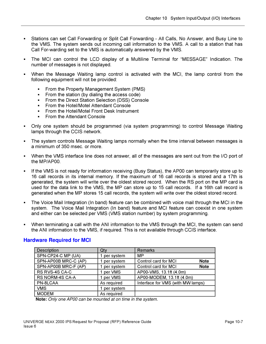
Description Qty Remarks
Message Center Interface MCI
Hardware Required for Smdr
Modem
Hardware Required for MCI
VMS
Type of Information
Feature
Feature
Property Management System PMS
PMS Interface
RS PRT-4S CA-A
Hardware Required for PMS
Description Qty Remarks
OpenWorX Business Attendant System BAS
Open Application Interface
System Outline
OpenWorX Attendant Statistics
BAS Call Control Functionality
Brief Description of Call Control Function
Brief Definition of Queues
Did for Company Lookup
BAS Speed Dials Pad
BAS Directory
BAS Call Recording and Playback
BAS Offline Mode Pseudo Night Mode
BAS Authorization and Account Code Dialing
BAS Overhead Paging
BR Overhead Paging
OpenWorX Business Receptionist BR
BR Speed Dials Pad
BR Directory
BR Attendant PC Minimum Hardware Requirements
BR Authorization and Account Code Dialing
OpenWorX Communications Portal
Communications Portal Benefits
Communications Portal Functionality
Dialer Benefits
OpenWorX Dialer
Dialer Database
OpenWorX Message Reader MR
OpenWorX Location Status Information LSI
STM Benefits
OpenWorX Short Text Messaging
MR Benefits
ICA Benefits
OpenWorX Incoming Call Assistant ICA
ICA Functionality
ICA ICA vs. Camp On
OpenWorX Group Call Forward Control Gcfc
ICA Comparison of ICA and IPS Functionality
Gcfc Functionality
OpenWorX Personal Call Assistant PCA
Personal Directory
PCA Limiting User Views
PCA OpenWorX Desktop
Desktop Directory
PCA OpenWorX Inaset
OpenWorX Name Display
Business Receptionist Ccis Network Information
OpenWorX Multiple Ccis Node Configuration
OAI Application Software Development
BAS Ccis Network Information
Page
Basic ACD
Automatic Call Distribution ACD with MIS
Automatic Call Distribution ACD
Call Waiting Indication ACD
Basic ACD Features
Delay Announcement ACD
Busy In/Busy Out ACD
Queue Size Control-ACD
CallCenterWorX ACD 3.0 for Business
Immediate Overflow ACD
Priority Queuing ACD
CallCenterWorX ACD Features
Automatic Call Distribution with MIS
CallCenterWorX ACD 3.0 for Business Turnkey Packages
CallCenterWorX MIS
Business Turnkey Packages
Business Software Only Packages
CallCenterWorX MIS
Bhca
Business System Capacities
Item ACD Capacities CallCenter WorX MIS
5GB
PBX Requirements Remarks
PBX Requirements
Related Documents
ACD Terminals
Contact Routing Q-Control
Master Contact Center Solutions
Master
Announcements Q-Announce
Reports Q-Control
Agent Desktop Q-Desktop
Multi-Media Q-Email, Q-Chat, Q-Fax
Callbacks Q-Callback
Interactive Voice Response Q-IVR
Outbound Dialing Q-Outdial
Auto Attendant
QueWorX 4.0 Features
QueWorX 4.0 Licensed Applications
Estimated Time to Answer ETA
Immediate Customer Callback
Scheduled Callbacks
Internet Initiated Callbacks
Global Repeat Verification
Screen Pop
Soft Phone
Multilingual Announcements
Customizable Reports
Professional Services for QueWorX
Customized Announcements
Voice over IP VoIP
VoIP Solutions
Extended Enterprise IP Solution
VoIP Solutions
Equipment Name Function
Typical IP Gateway, Branch and Adapter configurations
IP Station
Peer-to-Peer Connections over Ccis Networking via IP
Peer-to Peer Connections between IP Enabled Dterm
Remote Connections of IP Stations
Connections to Legacy Stations and Trunks
Automatic Program Download for IP Enabled Dterm
8IPLA/24IPLA
Options Per Location
Service Conditions on System Registration
Service Conditions on Legacy Service Features
MD5 is an algorithm defined in RFC 1321 from the Ietf
Service Conditions on Encryption in System Registration
Service Conditions on Vlan
Local Connection Mode Remote Connection Mode
Service Conditions on Remote Connections
Example 2 When Sta logs in Location #2
Location number in each operation mode for each IP station
Operation mode for each IP terminal
Example 1 When Sta logs in Location #1
Service Conditions on Automatic Program Download
SPN-16VCTAA IP PAD
Ccis Networking via IP
Required Equipment for IP Station
SPN-32IPLAA IP PAD
Ccis Networking via IP Peer-to-Peer Connections Basis
IP Trunk Point-to-Multipoint Connection
Ccis Networking via IP Non Peer-to-Peer Connections Basis
Point-to-Multipoint Connection
Payload Period Maximum Voice Channels per IP Trunk
Service Conditions IP Ccis via IP Trunk cards
IP Trunk Card Specifications
Required Equipment for IP Ccis via IP Trunk cards
Connection
Service Conditions for H.323
Features
Features
Required Equipment for H.323
IP Trunk Specifications
Example of FAX and Modem over IP connection
FAX and Modem over IP
SPN-32IPLA IP PAD-E
SPN-8IPLA IP PAD-C
SPN-8IPLA IP PAD-B
SPN-8IPLA IP PAD-A
Own
Required Equipment for FAX or Modem over IP
Opposite Office 2000 IPS
Opposite Office
Connection Conditions Required Bandwidth One-way
Required bandwidth for FAX Connection
Required bandwidth for Modem Connection
Requirement Remarks
Remote PIM over IP
Network Conditions and Payload
Compression
Bandwidth Requirement
With G7.23.1 With G729a 8k Without Compression 3k/6.3k
Advantages
Remote Site Equipment Name Remarks
Required Hardware and Software
Host Site Equipment Name Remarks
XNote
List of Service Features Operation
Bandwidth requirements
Planning and Installation
Vendor Support for Open System Standards
Voice Messaging
Network Bandwidth
Network Consideration
Codec Total Bandwidth per transmit stream Msec
Bandwidth utilization
Codec Filler Time Msec
Device Registration Server DRS and Dhcp
Quality of Service QoS
For Voice Control/Voice Packet
Port Type Destination Default Port No Remarks
For Dterm IP
PBX TCP
For Ccis Virtual IPT
For H.323 IP Trunk
IPT Ccis
Conditions
System Conditions/Limitations Peer-to-Peer IP
Limitations
Common Channel Inter-Office Signaling Ccis
System Outline of a Ccis Connection
Ccis and Isdn
Analog Ccis
Digital and Analog Ccis
Digital Ccis
Voice Compression
Peer-to-Peer Connections
Common Channel Inter-Office Signaling Ccis
Ccis Networking via IP Non Peer-to-Peer
Service Conditions on Non Peer-to-Peer Connections
Center office
Centralized Billing
Local office/Tandem office
Common Channel Inter-Office Signaling Ccis
Centralized E911 Ccis
Look Ahead Routing
Call Set Up Times
Alternate Routing
Shared Trunk Facilities and Alternate Routing
Centralized Management Center
Centralized System Maintenance and Administration
Centralized Maintenance Facility
Centralized Call Accounting / Billing
Centralized Call Accounting/Billing Systems
Ccis Centralized Voice Mail
Centralized Voice Processing / Messaging
Centralized Attendant Consoles
YES
Ccis Feature Chart
Ccis Feature Name Neax 2400 Required
Uniform Numbering Plans
Ccis Feature Chart
System Capacity for Ccis Networking via IP
System Capacity
System Capacity for Ccis with Digital Interface
System Capacity for Ccis with Analog Interface
Required Equipment for Ccis Networking via IP
Required Equipment
Required Equipment for Digital Ccis
Required Equipment for Analog Ccis
24IPLA
IP Specifications
Specifications Remarks
PAD
Characteristics Channel
DTI Specifications
Page
Isdn Primary Rate Interface
Integrated Services Data Network Isdn
PRI Services & Features
Isdn Feature List
CPN To Network-Present
Call-By-Call Service Selection
Called Party Recognition Service Direct-In Termination DIT
CPN To Terminating User-Display
AT&T
Did Addressing
Did and DOD Addressing
Isdn Terminal
Page
Subaddress-Present
Megacom Access/WATS
Megacom 800 Service/800 Wats Ultra Wats
Multiquest /900 Service
Event Based Ccis
Trunk Provisioning Service Selection
Business Feature List
Business Feature List
Isdn Network Requirements for Layer One
Supported Network Services Trunk provisioned only
For 24PRT
Isdn PRI Specifications
For 24DTI
For 30DTI
BRT
DMS Provisioning 4ESS NET
Dedicated Access AT&T NTI MCI Sprint
DMS Selection 4ESS NET
NET IPS
AT&T NTI MCI Sprint
Voice Features DMS 4ESS NET
AT&T MCI Sprint Virtual Private Network DMS 4ESS NET
AT&T MCI Sprint Selection DMS 4ESS NET IPS Switched Data
Dedicated Access NTI
AT&T MCI Sprint Provisioning DMS 4ESS NET IPS Switched Data
Virtual Private Network AT&T NTI DMS 4ESS NET
Services and Features LEC Carriers
Call by Call Service AT&T NTI Siemens Selection 5ESS
Dedicated Access AT&T NTI Siemens
Network Message Waiting
Voice Features AT&T NTI Siemens
AT&T NTI Siemens
Facility Management
Virtual Private Network AT&T NTI Siemens
Call By Call Service Selection
Ewsd Switched Data
AT&T NTI Siemens 5ESS
Applications
Isdn Basic Rate Interface BRI
ONE SC03 Supports Four 2ILCA
System Requirements
Isdn Terminal Required Equipment
Isdn Equipment List
Isdn PRI Required Equipment
Isdn BRI Required Equipment
24DTI 24PRT
Documentation
Capacity for ISDN-PRI
System Capacity for ISDN-BRI
Page
Analog PBX Interface
Wireless System
Univerge Neax 2000 IPS Wireless Communication System WCS
Wired for Wireless
Ccis Interface
Wireless Roaming
Multi-Site Roaming
931a Roaming over IP Trunk
HLR
Wireless Definitions
Configuration Application Integrated Type
Wireless Short Text Message Notification OAI
Adjunct Type Integrated Type
Features
Feature Matrix by Configuration Type
2000 IPS Interface1 Interface2 Wired for Wireless
Feature Descriptions
Handover
Wired for
Wireless
Way Calling
Indication
Authorization
Preset Dialing
Out of Zone
Dterm PS
System Description
Headsets
Dterm PS III Accessories
Lithium-Ion Battery
Battery Charger
Zone Transceiver II ZT
Integrated Adjunct Analog Adjunct Ccis
Wireless Specifications
Zone Transceiver II Specifications
Equipment Description QTY Remarks
WCS Required Equipment
PN-4VCTI 4VCT
PN-IPTB IPT
Wireless LAN Documentation
Wireless LAN
Wireless LAN Handset
Terminal Console
Hotel Feature List
Hotel/Motel System
PMS
Station Message Detail Recording Smdr
Application Processor
Hotel Console
Hotel/Motel Front Desk Terminal
Executed Task Print Out
Hotel Printer
Automatic Wake-up
Check
Check In / Check Out
Direct Data Entry
Do Not Disturb Console
Hotel/Motel Attendant Console
Do Not Disturb-Hotel/Motel
Do Not Disturb-System
Hotel/Motel Front Desk Instrument
Maid Status
House Phone
Voice Message Waiting Individual
Message Registration
Message Waiting
Voice Message Waiting System
Property Management System PMS
Room Cutoff Console
Room Cutoff
Items indicated are as follows
Room Status
Single Digit Dialing
Description Capacity
Specifications PMS/SMDR Interface Hotel Printer Interface
Hotel System Capacity
SN716 Deskcon
Station Equipment
AIMWorX
Call Accounting
Select Database Licensing Option Description
Multi-Site Centralized Operations
AIMWorX databases
Licensing
Information you need before installing AIMWorX
SQL Server licensing
Oracle database
Call Record and User Capacity
Configurations
Standalone
Enterprise tier
AIMWorX Manager
Integrating AIMWorX modules
Corporate tier
Auth Code Manager
Alarm Manager
1 SPE
Asset Manager
Hospitality Links
Bill Reconciler
Cable Manager
Custom SPE Writer
Work Order
Additional Reference Material
Trouble Ticket
Voice Mail SPE
Voice Mail Integration
Voice Messaging Systems
Voice Messaging Systems
Description
MCI Service Conditions
System Architecture
NEAXMail AD-120
Level II Server Software License with Exchange
Voice Cards
Platform Components
Client Access Licenses CAL
Third Party Software
PBX Integration Software
Optional Software Feature Packages
Mail Reader Text-to-Speech
Third Party Fax Server Integration
2GB
Platform Specifications
NEAXMail AD-64
40GB Sata 36GB Scsi
Level I/Level II Platform Specifications
Level I/Level II Specifications Platform Level
Level I Dell GX280 Level II Dell PE2800
Optional ActiveFax Software
UPS Uninterruptible Power Supply
Additional Hardware Components
Optional Software
Unified Messaging
Hacker Prevention Features are as follows
Voice Messaging Systems
Voice Messaging Systems
Available Languages
Automated Attendant
Mailbox Manager
Audiotext
Voice Messaging Systems
Maintenance
Voice Messaging Systems
ViewMail
Visual Messaging
ViewCall Plus
Full Digital Integration
NEAXMail IM-16 LX
Unified Messaging and Call Management
Enjoy the Benefits of Integrated Messaging
Hospitality Feature Package
Basic Features
Additional Features
Univerge Neax 2000 IPS Technical Manuals
Niverge Neax 2000 IPS Features and Specification
System Documentation
Univerge Neax 2000 IPS Documentation List