| 6 | 7 | 8 | 9 |
|
| |
|
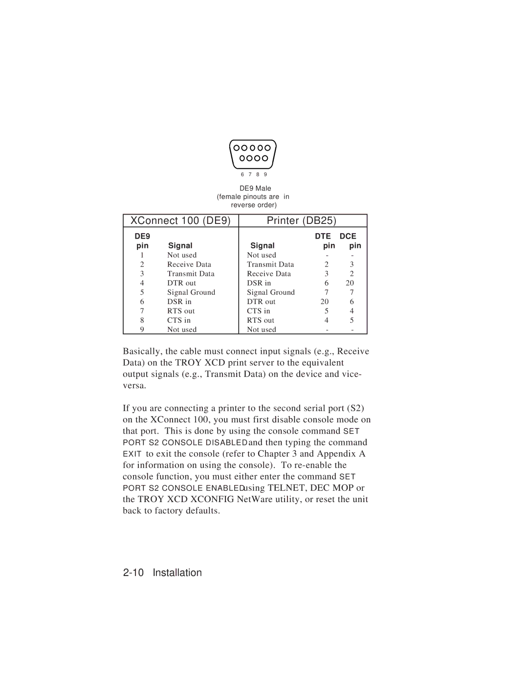
| DE9 Male |
|
| |||
| (female pinouts are in |
|
| ||||
| reverse order) |
|
| ||||
|
|
|
| ||||
XConnect 100 (DE9) |
|
|
| Printer (DB25) | |||
DE9 |
|
|
|
|
| DTE | DCE |
pin | Signal |
| Signal | pin | pin | ||
1 | Not used |
| Not used | - | - | ||
2 | Receive Data |
| Transmit Data | 2 | 3 | ||
3 | Transmit Data |
| Receive Data | 3 | 2 | ||
4 | DTR out |
| DSR in | 6 | 20 | ||
5 | Signal Ground |
| Signal Ground | 7 | 7 | ||
6 | DSR in |
| DTR out | 20 | 6 | ||
7 | RTS out |
| CTS in | 5 | 4 | ||
8 | CTS in |
| RTS out | 4 | 5 | ||
9 | Not used |
| Not used | - | - | ||
Basically, the cable must connect input signals (e.g., Receive Data) on the TROY XCD print server to the equivalent output signals (e.g., Transmit Data) on the device and vice- versa.
If you are connecting a printer to the second serial port (S2) on the XConnect 100, you must first disable console mode on that port. This is done by using the console command SET
and then typing the command EXIT to exit the console (refer to Chapter 3 and Appendix A for information on using the console). To
using TELNET, DEC MOP or the TROY XCD XCONFIG NetWare utility, or reset the unit back to factory defaults.