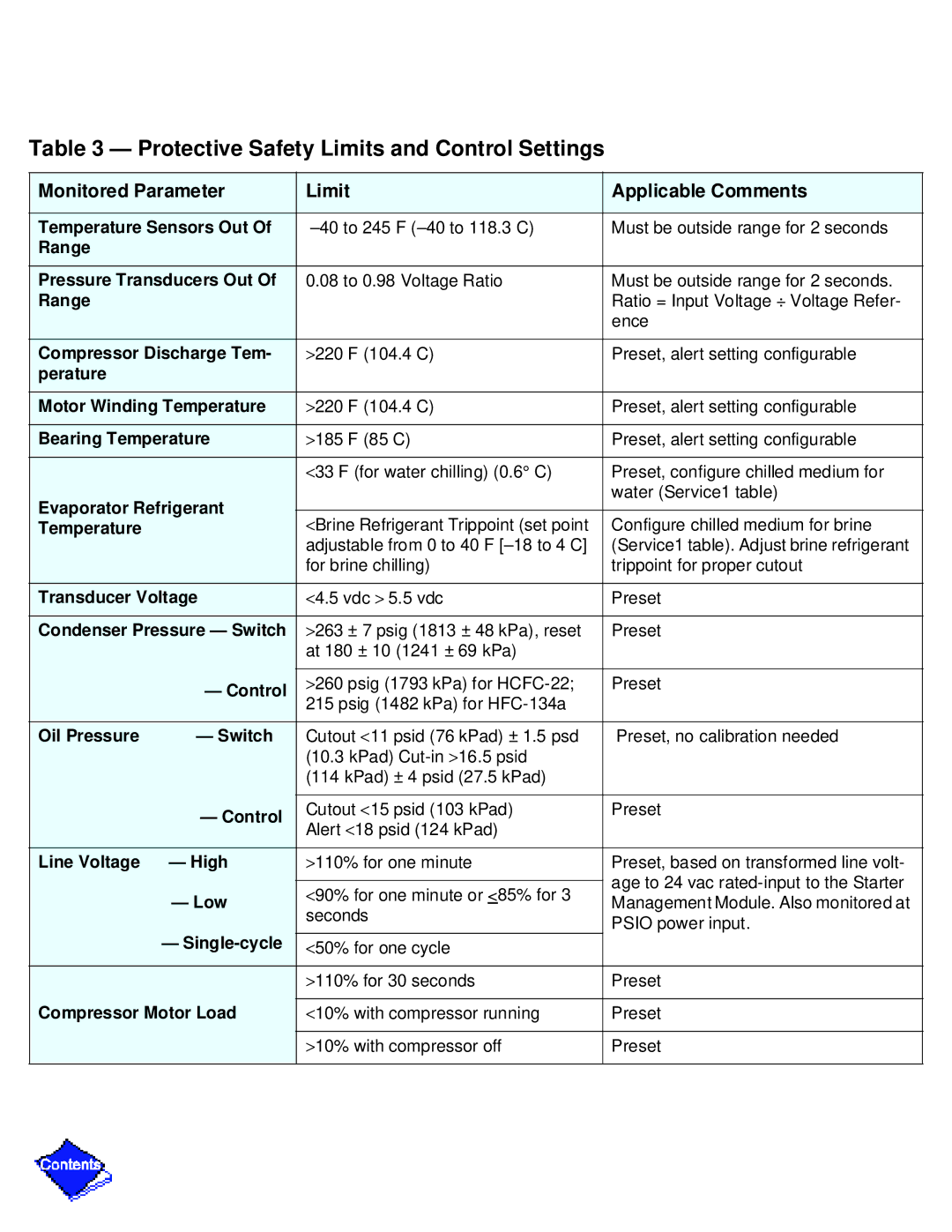
Table 3 — Protective Safety Limits and Control Settings
Monitored Parameter | Limit | Applicable Comments | ||
|
|
| ||
Temperature Sensors Out Of | Must be outside range for 2 seconds | |||
Range |
|
|
| |
|
|
| ||
Pressure Transducers Out Of | 0.08 to 0.98 Voltage Ratio | Must be outside range for 2 seconds. | ||
Range |
|
| Ratio = Input Voltage ÷ Voltage Refer- | |
|
|
| ence | |
|
|
| ||
Compressor Discharge Tem- | >220 F (104.4 C) | Preset, alert setting configurable | ||
perature |
|
|
| |
|
|
| ||
Motor Winding Temperature | >220 F (104.4 C) | Preset, alert setting configurable | ||
|
|
| ||
Bearing Temperature | >185 F (85 C) | Preset, alert setting configurable | ||
|
|
|
| |
|
| <33 F (for water chilling) (0.6° C) | Preset, configure chilled medium for | |
Evaporator Refrigerant |
| water (Service1 table) | ||
|
| |||
<Brine Refrigerant Trippoint (set point | Configure chilled medium for brine | |||
Temperature |
| |||
|
| adjustable from 0 to 40 F | (Service1 table). Adjust brine refrigerant | |
|
| for brine chilling) | trippoint for proper cutout | |
|
|
| ||
Transducer Voltage | <4.5 vdc > 5.5 vdc | Preset | ||
|
|
| ||
Condenser Pressure — Switch | >263 ± 7 psig (1813 ± 48 kPa), reset | Preset | ||
|
| at 180 ± 10 (1241 ± 69 kPa) |
| |
|
|
|
| |
| — Control | >260 psig (1793 kPa) for | Preset | |
| 215 psig (1482 kPa) for |
| ||
|
|
| ||
|
|
|
| |
Oil Pressure | — Switch | Cutout <11 psid (76 kPad) ± 1.5 psd | Preset, no calibration needed | |
|
| (10.3 kPad) |
| |
|
| (114 kPad) ± 4 psid (27.5 kPad) |
| |
|
|
|
| |
| — Control | Cutout <15 psid (103 kPad) | Preset | |
| Alert <18 psid (124 kPad) |
| ||
|
|
| ||
|
|
|
| |
Line Voltage | — High | >110% for one minute | Preset, based on transformed line volt- | |
|
|
| age to 24 vac | |
| — Low | <90% for one minute or <85% for 3 | ||
| Management Module. Also monitored at | |||
| seconds | |||
|
| PSIO power input. | ||
| — |
| ||
| <50% for one cycle |
| ||
|
|
|
| |
|
| >110% for 30 seconds | Preset | |
|
|
| ||
Compressor Motor Load | <10% with compressor running | Preset | ||
|
|
|
| |
|
| >10% with compressor off | Preset | |
|
|
|
| |