M a k i n g M e a s u r e m e n t s U s i n g S p e c t r u m A n a l y z e r M o d e
Using the
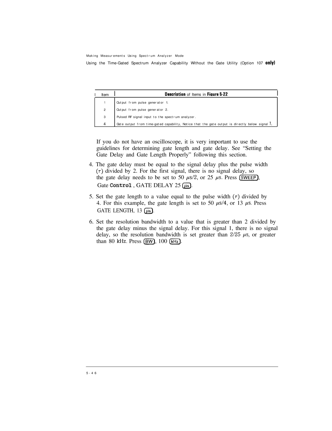
I | Item | I | Descriution of Items in Fiaure 5.22 |
1
2
3
4
Output from pulse generator 1 . Output from pulse generator 2 .
Pulsed RF signal input to the spectrum analyzer .
Gate output from time - gated capability, Notice that the gate output is directly below signal 1.
If you do not have an oscilloscope, it is very important to use the guidelines for determining gate length and gate delay. See “Setting the Gate Delay and Gate Length Properly” following this section.
4.The gate delay must be equal to the signal delay plus the pulse width
(7)divided by 2. For the first signal, there is no signal delay, so
the gate delay needs to be set to 50 &2, or 25 +s. Press Cm], Gate Contra1 , GATE DELAY 25 @J.
5.Set the gate length to a value equal to the pulse width (T) divided by
4.For this example, the gate length is set to 50 ,us/4, or 13 ps. Press
GATE LENGTH, 13 @.
6.Set the resolution bandwidth to a value that is greater than 2 divided by the gate delay minus the signal delay. For this signal 1, there is no signal delay, so the resolution bandwidth is set greater than 2/25 ps, or greater than 80 kHz. Press Isw), 100 IkHz).
5 - 4 6