Implementing External GMII
R
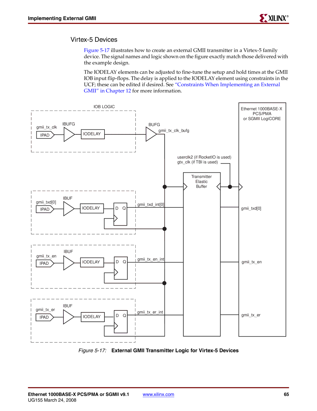
Virtex-5 Devices
Figure 5-17 illustrates how to create an external GMII transmitter in a Virtex-5 family device. The signal names and logic shown on the figure exactly match those delivered with the example design.
The IODELAY elements can be adjusted to fine-tune the setup and hold times at the GMII IOB input flip-flops. The delay is applied to the IODELAY element using constraints in the UCF; these can be edited if desired. See “Constraints When Implementing an External GMII” in Chapter 12 for more information.
gmii_tx_clk
IPAD
gmii_txd[0]
IPAD
gmii_tx_en
IPAD
gmii_tx_er
IPAD
|
| IOB LOGIC |
| |
IBUFG |
|
|
| BUFG |
|
|
|
| gmii_tx_clk_bufg |
|
| IODELAY |
| |
|
|
|
| |
|
|
|
| |
|
|
|
|
|
userclk2 (if RocketIO is used) gtx_clk (if TBI is used)
Transmitter
Elastic
Buffer
IBUF
|
|
|
| gmii_txd_int[0] |
| IODELAY |
| D Q | |
|
|
| ||
|
| |||
|
|
|
|
|
IBUF
|
|
| D Q | gmii_tx_en_int |
| IODELAY |
| ||
|
|
| ||
|
|
|
|
|
IBUF
|
|
| gmii_tx_er_int |
| IODELAY |
| D Q |
|
| ||
|
|
|
|
Ethernet
or SGMII LogiCORE
gmii_txd[0]
gmii_tx_en
gmii_tx_er
Figure 5-17: External GMII Transmitter Logic for Virtex-5 Devices
Ethernet | www.xilinx.com | 65 |