Required Constraints
R
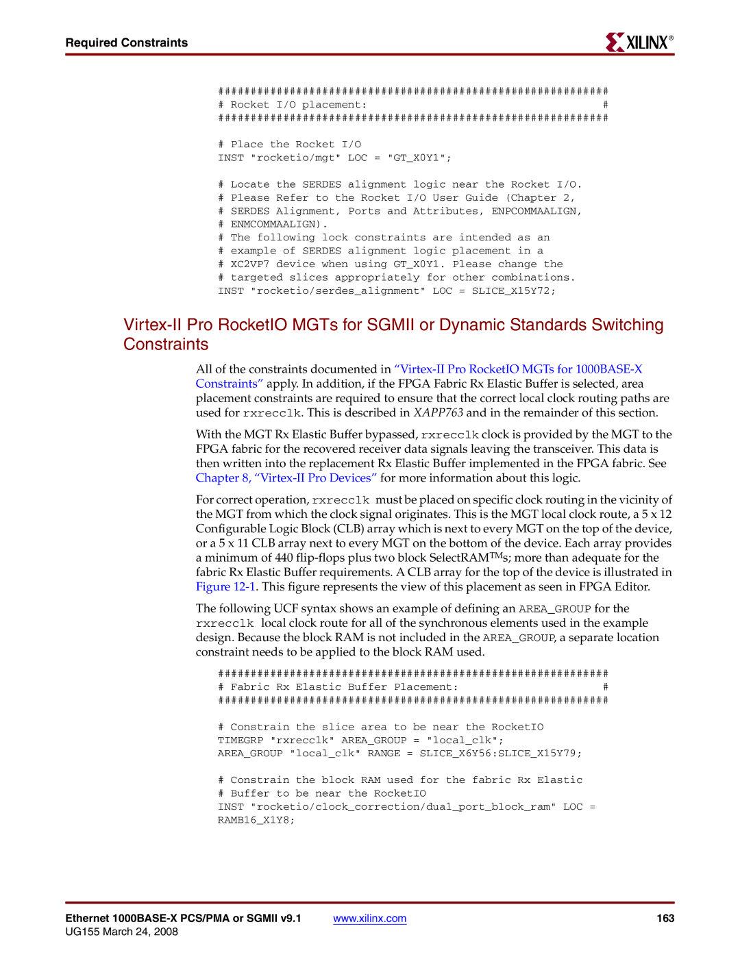
############################################################
# Rocket I/O placement:#
############################################################
# Place the Rocket I/O
INST "rocketio/mgt" LOC = "GT_X0Y1";
#Locate the SERDES alignment logic near the Rocket I/O.
#Please Refer to the Rocket I/O User Guide (Chapter 2,
#SERDES Alignment, Ports and Attributes, ENPCOMMAALIGN,
#ENMCOMMAALIGN).
#The following lock constraints are intended as an
#example of SERDES alignment logic placement in a
#XC2VP7 device when using GT_X0Y1. Please change the
#targeted slices appropriately for other combinations. INST "rocketio/serdes_alignment" LOC = SLICE_X15Y72;
All of the constraints documented in
With the MGT Rx Elastic Buffer bypassed, rxrecclk clock is provided by the MGT to the FPGA fabric for the recovered receiver data signals leaving the transceiver. This data is then written into the replacement Rx Elastic Buffer implemented in the FPGA fabric. See Chapter 8,
For correct operation, rxrecclk must be placed on specific clock routing in the vicinity of the MGT from which the clock signal originates. This is the MGT local clock route, a 5 x 12 Configurable Logic Block (CLB) array which is next to every MGT on the top of the device, or a 5 x 11 CLB array next to every MGT on the bottom of the device. Each array provides
aminimum of 440
The following UCF syntax shows an example of defining an AREA_GROUP for the rxrecclk local clock route for all of the synchronous elements used in the example design. Because the block RAM is not included in the AREA_GROUP, a separate location constraint needs to be applied to the block RAM used.
############################################################
# Fabric Rx Elastic Buffer Placement:#
############################################################
#Constrain the slice area to be near the RocketIO TIMEGRP "rxrecclk" AREA_GROUP = "local_clk"; AREA_GROUP "local_clk" RANGE = SLICE_X6Y56:SLICE_X15Y79;
#Constrain the block RAM used for the fabric Rx Elastic
#Buffer to be near the RocketIO
INST "rocketio/clock_correction/dual_port_block_ram" LOC =
RAMB16_X1Y8;
Ethernet | www.xilinx.com | 163 |