MDIO Management Interface
Table 9-1: Abbreviations and Terms (Continued)
Abbreviation | Term |
|
|
PHYAD | Physical address |
|
|
REGAD | Register address |
|
|
TA | Turnaround |
|
|
R
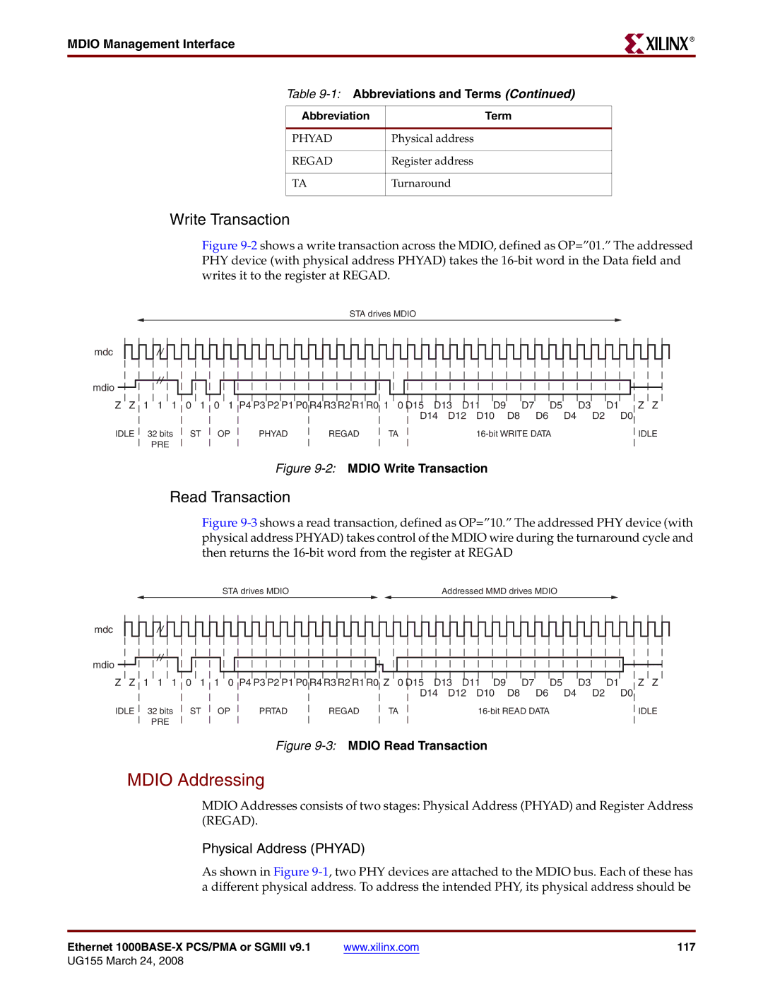
Write Transaction
Figure 9-2 shows a write transaction across the MDIO, defined as OP=”01.” The addressed PHY device (with physical address PHYAD) takes the 16-bit word in the Data field and writes it to the register at REGAD.
STA drives MDIO
mdc
mdio
Z Z | 1 1 1 | 0 1 | 0 1 P4 P3 P2 P1 P0 R4 R3 R2 R1 R0 1 0 D15 D13 D11 D9 |
| D7 D5 | D3 | D1 | Z Z | |||||
|
|
|
|
|
| D14 | D12 | D10 | D8 | D6 | D4 | D2 | D0 |
IDLE | 32 bits | ST | OP | PHYAD | REGAD | TA |
|
|
| IDLE | |||
| PRE |
|
|
|
|
|
|
|
|
|
|
|
|
Figure 9-2: MDIO Write Transaction
Read Transaction
Figure 9-3 shows a read transaction, defined as OP=”10.” The addressed PHY device (with physical address PHYAD) takes control of the MDIO wire during the turnaround cycle and then returns the 16-bit word from the register at REGAD
STA drives MDIO |
| Addressed MMD drives MDIO |
mdc
mdio
Z Z | 1 1 1 | 0 1 | 1 0 P4 P3 P2 P1 P0 R4 R3 R2 R1 R0 Z 0 D15 D13 D11 D9 |
| D7 D5 | D3 | D1 | Z Z | |||||
|
|
|
|
|
| D14 | D12 | D10 | D8 | D6 | D4 | D2 | D0 |
IDLE | 32 bits | ST | OP | PRTAD | REGAD | TA |
|
|
| IDLE | |||
| PRE |
|
|
|
|
|
|
|
|
|
|
|
|
Figure 9-3: MDIO Read Transaction
MDIO Addressing
MDIO Addresses consists of two stages: Physical Address (PHYAD) and Register Address (REGAD).
Physical Address (PHYAD)
As shown in Figure
Ethernet | www.xilinx.com | 117 |