Core Interfaces
R
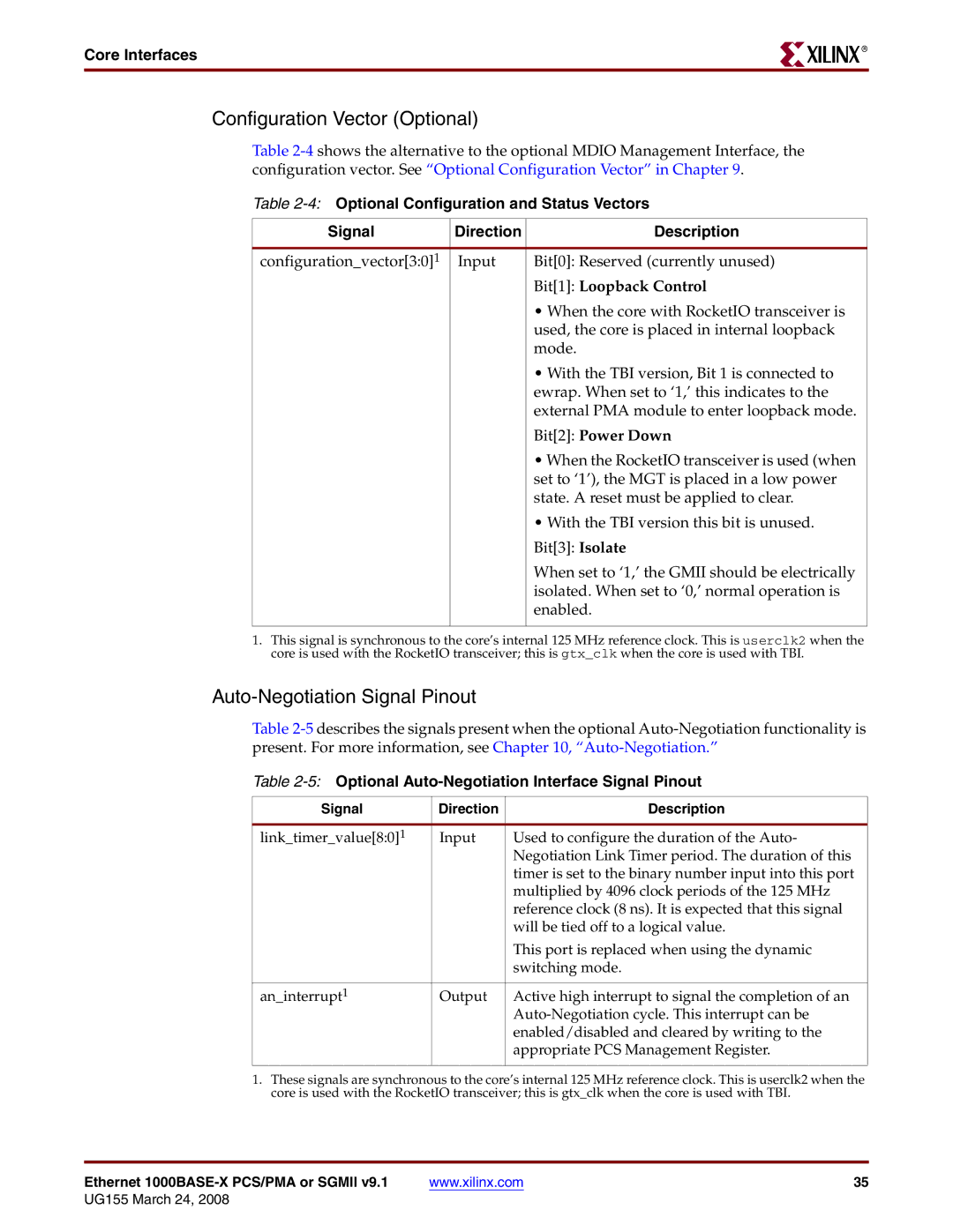
Configuration Vector (Optional)
Table
Table
Signal | Direction | Description |
|
|
|
configuration_vector[3:0]1 | Input | Bit[0]: Reserved (currently unused) |
|
| Bit[1]: Loopback Control |
|
| • When the core with RocketIO transceiver is |
|
| used, the core is placed in internal loopback |
|
| mode. |
|
| • With the TBI version, Bit 1 is connected to |
|
| ewrap. When set to ‘1,’ this indicates to the |
|
| external PMA module to enter loopback mode. |
|
| Bit[2]: Power Down |
|
| • When the RocketIO transceiver is used (when |
|
| set to ‘1’), the MGT is placed in a low power |
|
| state. A reset must be applied to clear. |
|
| • With the TBI version this bit is unused. |
|
| Bit[3]: Isolate |
|
| When set to ‘1,’ the GMII should be electrically |
|
| isolated. When set to ‘0,’ normal operation is |
|
| enabled. |
|
|
|
1.This signal is synchronous to the core’s internal 125 MHz reference clock. This is userclk2 when the core is used with the RocketIO transceiver; this is gtx_clk when the core is used with TBI.
Auto-Negotiation Signal Pinout
Table
Table 2-5: Optional Auto-Negotiation Interface Signal Pinout
Signal | Direction | Description |
|
|
|
link_timer_value[8:0]1 | Input | Used to configure the duration of the Auto- |
|
| Negotiation Link Timer period. The duration of this |
|
| timer is set to the binary number input into this port |
|
| multiplied by 4096 clock periods of the 125 MHz |
|
| reference clock (8 ns). It is expected that this signal |
|
| will be tied off to a logical value. |
|
| This port is replaced when using the dynamic |
|
| switching mode. |
|
|
|
an_interrupt1 | Output | Active high interrupt to signal the completion of an |
|
| |
|
| enabled/disabled and cleared by writing to the |
|
| appropriate PCS Management Register. |
|
|
|
1.These signals are synchronous to the core’s internal 125 MHz reference clock. This is userclk2 when the core is used with the RocketIO transceiver; this is gtx_clk when the core is used with TBI.
Ethernet | www.xilinx.com | 35 |