Design Overview
R
1000BASE-X Standard with TBI Example Design
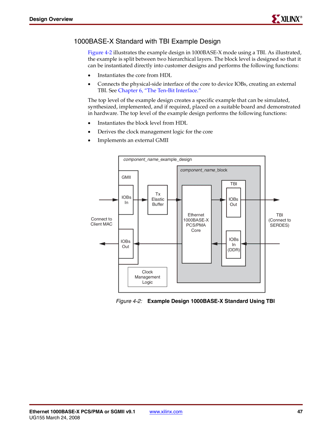
Figure 4-2 illustrates the example design in 1000BASE-X mode using a TBI. As illustrated, the example is split between two hierarchical layers. The block level is designed so that it can be instantiated directly into customer designs and performs the following functions:
•Instantiates the core from HDL
•Connects the physical-side interface of the core to device IOBs, creating an external TBI. See Chapter 6, “The Ten-Bit Interface.”
The top level of the example design creates a specific example that can be simulated, synthesized, implemented, and if required, placed on a suitable board and demonstrated in hardware. The top level of the example design performs the following functions:
•Instantiates the block level from HDL
•Derives the clock management logic for the core
•Implements an external GMII
component_name_example_design |
| |
| component_name_block |
|
GMII |
|
|
|
| TBI |
IOBs | Tx |
|
Elastic | IOBs | |
In | Buffer | Out |
| ||
Connect to | Ethernet | TBI |
(Connect to | ||
Client MAC | PCS/PMA | SERDES) |
| Core |
|
IOBs |
| IOBs |
| In | |
Out |
| |
| (DDR) | |
|
| |
| Clock |
|
| Management |
|
| Logic |
|
Figure | ||
Ethernet | www.xilinx.com | 47 |