Xilinx 1000BASE-X manual Bits42 Code Group Reception Indicators, Gmii Transmission

Models: 1000BASE-X

1 230
Download 230 pages 37.04 Kb
Page 57
Image 57

Designing with the Client-side GMII for the 1000BASE-X Standard

R

Bits[4:2]: Code Group Reception Indicators

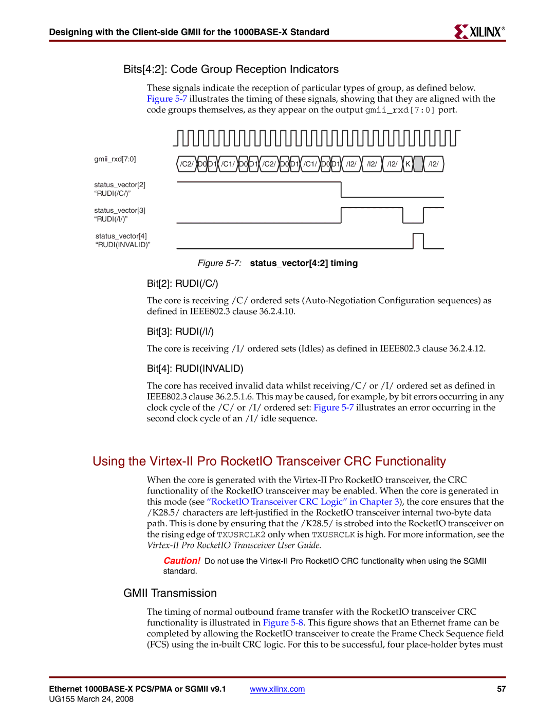
These signals indicate the reception of particular types of group, as defined below. Figure 5-7illustrates the timing of these signals, showing that they are aligned with the code groups themselves, as they appear on the output gmii_rxd[7:0] port.

gmii_rxd[7:0]

/C2/ D0 D1 /C1/ D0 D1 /I2/ /I2/ /I2/ K

/I2/

/C2/ D0 D1 /C1/ D0 D1

status_vector[2] “RUDI(/C/)”

status_vector[3] “RUDI(/I/)”

status_vector[4] “RUDI(INVALID)”

Figure 5-7:status_vector[4:2] timing

Bit[2]: RUDI(/C/)

The core is receiving /C/ ordered sets (Auto-Negotiation Configuration sequences) as defined in IEEE802.3 clause 36.2.4.10.

Bit[3]: RUDI(/I/)

The core is receiving /I/ ordered sets (Idles) as defined in IEEE802.3 clause 36.2.4.12.

Bit[4]: RUDI(INVALID)

The core has received invalid data whilst receiving/C/ or /I/ ordered set as defined in IEEE802.3 clause 36.2.5.1.6. This may be caused, for example, by bit errors occurring in any clock cycle of the /C/ or /I/ ordered set: Figure 5-7illustrates an error occurring in the second clock cycle of an /I/ idle sequence.

Using the Virtex-II Pro RocketIO Transceiver CRC Functionality

When the core is generated with the Virtex-II Pro RocketIO transceiver, the CRC functionality of the RocketIO transceiver may be enabled. When the core is generated in this mode (see “RocketIO Transceiver CRC Logic” in Chapter 3), the core ensures that the /K28.5/ characters are left-justified in the RocketIO transceiver internal two-byte data path. This is done by ensuring that the /K28.5/ is strobed into the RocketIO transceiver on the rising edge of TXUSRCLK2 only when TXUSRCLK is high. For more information, see the Virtex-II Pro RocketIO Transceiver User Guide.

Caution! Do not use the Virtex-II Pro RocketIO CRC functionality when using the SGMII standard.

GMII Transmission

The timing of normal outbound frame transfer with the RocketIO transceiver CRC functionality is illustrated in Figure 5-8. This figure shows that an Ethernet frame can be completed by allowing the RocketIO transceiver to create the Frame Check Sequence field (FCS) using the in-built CRC logic. For this to be successful, four place-holder bytes must

Ethernet 1000BASE-X PCS/PMA or SGMII v9.1

www.xilinx.com

57

UG155 March 24, 2008

Page 57
Image 57
Xilinx 1000BASE-X manual Bits42 Code Group Reception Indicators, Gmii Transmission