Core Interfaces
R
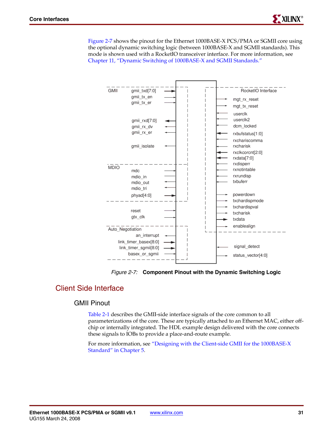
Figure 2-7 shows the pinout for the Ethernet 1000BASE-X PCS/PMA or SGMII core using the optional dynamic switching logic (between 1000BASE-X and SGMII standards). This mode is shown used with a RocketIO transceiver interface. For more information, see Chapter 11, “Dynamic Switching of 1000BASE-X and SGMII Standards.”
GMII gmii_txd[7:0] gmii_tx_en gmii_tx_er
RocketIO Interface
mgt_rx_reset mgt_tx_reset
MDIO
gmii_rxd[7:0] gmii_rx_dv gmii_rx_er
gmii_isolate
mdc mdio_in mdio_out mdio_tri
phyad[4:0]
userclk userclk2 dcm_locked
rxbufstatus[1:0]
rxchariscomma rxcharisk
rxclkcorcnt[2:0]
rxdata[7:0] rxdisperr rxnotintable
rxrundisp txbuferr
powerdown txchardispmode txchardispval
reset gtx_clk
Auto_Negotiation an_interrupt
link_timer_basex[8:0] link_timer_sgmii[8:0] basex_or_sgmii
txcharisk txdata enablealign
signal_detect
status_vector[4:0]
Figure 2-7: Component Pinout with the Dynamic Switching Logic
Client Side Interface
GMII Pinout
Table
For more information, see “Designing with the
Standard” in Chapter 5.
Ethernet | www.xilinx.com | 31 |