R
Chapter 4: Designing with the Core
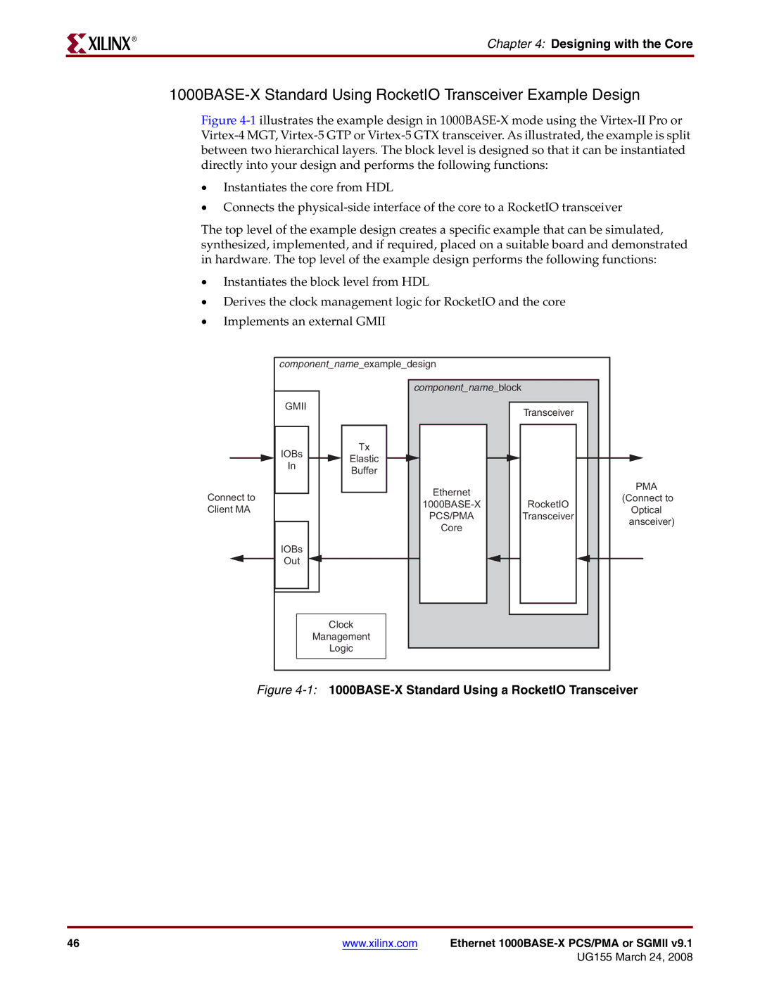
Figure 4-1 illustrates the example design in 1000BASE-X mode using the Virtex-II Pro or Virtex-4 MGT, Virtex-5 GTP or Virtex-5 GTX transceiver. As illustrated, the example is split between two hierarchical layers. The block level is designed so that it can be instantiated directly into your design and performs the following functions:
•Instantiates the core from HDL
•Connects the physical-side interface of the core to a RocketIO transceiver
The top level of the example design creates a specific example that can be simulated, synthesized, implemented, and if required, placed on a suitable board and demonstrated in hardware. The top level of the example design performs the following functions:
•Instantiates the block level from HDL
•Derives the clock management logic for RocketIO and the core
•Implements an external GMII
component_name_example_design |
|
| ||
| component_name_block |
|
| |
GMII |
| Transceiver |
| |
|
|
| ||
IOBs | Tx |
|
| |
Elastic |
|
| ||
In |
|
| ||
Buffer |
|
| ||
|
|
| ||
| Ethernet |
| PMA | |
Connect to |
| (Connect to | ||
RocketIO | ||||
Client MA | Optical | |||
PCS/PMA | Transceiver | |||
| ansceiver) | |||
| Core |
| ||
|
|
| ||
IOBs |
|
|
| |
Out |
|
|
| |
| Clock |
|
| |
Management |
|
| ||
| Logic |
|
| |
Figure | ||||
46 | www.xilinx.com | Ethernet |
