PROCEDURES | SENSOR ZERO/CAL |
|
| Any error conditions encountered during calibration, for example the pres- | ||||||
|
| ence of extraneous noise or RF signals, will result in an error message on | ||||||
|
| the front panel display. |
|
| ||||
|
| The sensors can also be calibrated using the GPIB CAL command (see | ||||||
|
| Chapter 6, GPIB Operation). |
|
| ||||
SENSOR ZERO/CAL | Sensors must be zeroed before being calibrated. The Zero/Cal function | |||||||
|
| completes both operations in sequence. | ||||||
|
| To zero and calibrate the sensor, connect the sensor to the ML2430A Se- | ||||||
|
| ries 50 MHz, 0.0 dBm reference output connector labeled CALIBRATOR. | ||||||
|
| When the sensor is first attached, the message SENSOR x NOT ZERO- | ||||||
|
| ED (where x = A or B as appropriate) is displayed. | ||||||
|
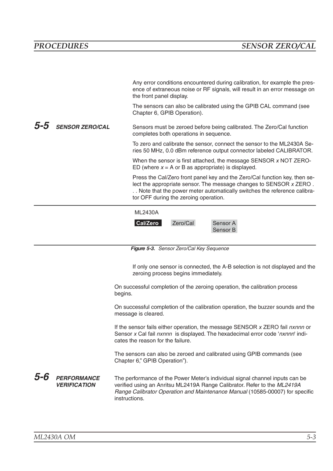
| Press the Cal/Zero front panel key and the Zero/Cal function key, then se- | ||||||
|
| lect the appropriate sensor. The message changes to SENSOR x ZERO . | ||||||
|
| . . Note that the power meter automatically switches the reference calibra- | ||||||
|
| tor OFF during the zeroing operation. | ||||||
|
|
|
|
|
|
|
| |
|
|
| ML2430A |
|
|
|
| |
|
|
|
|
|
|
|
| |
|
|
| Cal/Zero |
| Zero/Cal |
| Sensor A |
|
|
|
|
|
|
|
| Sensor B |
|
|
|
| ||||||
|
| Figure | ||||||
|
| If only one sensor is connected, the | ||||||
|
| zeroing process begins immediately. | ||||||
|
| On successful completion of the zeroing operation, the calibration process | ||||||
|
| begins. |
|
|
|
| ||
|
| On successful completion of the calibration operation, the buzzer sounds and the | ||||||
|
| message is cleared. |
|
|
|
| ||
|
| If the sensor fails either operation, the message SENSOR x ZERO fail nxnnn or | ||||||
|
| Sensor x Cal fail nxnnn is displayed. The hexadecimal error code 'nxnnn' indi- | ||||||
|
| cates the reason for the failure. |
|
| ||||
|
| The sensors can also be zeroed and calibrated using GPIB commands (see | ||||||
|
| Chapter 6,” GPIB Operation”). |
|
| ||||
PERFORMANCE | The performance of the Power Meter’s individual signal channel inputs can be | |||||||
| VERIFICATION | verified using an Anritsu ML2419A Range Calibrator. Refer to the ML2419A | ||||||
|
| Range Calibrator Operation and Maintenance Manual | ||||||
|
| instructions. |
|
|
|
| ||
ML2430A OM | |
|
|