ML4803A EMULATION COMMANDS | GPIB OPERATION |
| This section provides an alphabetical listing of the GPIB commands (mnemonics) | ||
EMULATION | used to program the Model ML2430A Series Power Meter in ML4803A mode. | ||
COMMANDS | The emulation mode can be set through the front panel | ||
| SYSTEMmoremoreRear panelGPIBMODE menu (see Chapter 4, Operation) | ||
| or through the GPIB command EMUL (page | ||
| All ML4803A GPIB commands that use parameters must not have a space be- | ||
| tween the command header and the parameter. Multiple parameters must be | ||
| separated by semicolons. |
| |
| Multiple commands may be sent on the same line, but must be separated by | ||
| spaces. |
|
|
| The format for ML4803A GPIB commands is: | ||
| <command header><parameter 1>;<parameter n>;... | ||
| The end of the command text must be terminated with a line feed character (0Ah, | ||
| decimal 10) or a GPIB End of Transmission State (EOI), or both. | ||
| The ML4803A has an array of memory addresses that each hold a structure of | ||
| four values; Frequency, Cal factor, Offset, and Reference. The data held for an | ||
| entered frequency is not automatically applied, but only applied if that memory | ||
| address is called. The frequency value is only a reference to the operator for | ||
| which the cal factor and other data is relevant. These memory address sets of | ||
| data are only available via the GPIB in ML4803A emulation mode. | ||
SRQ’s | The startup and default mode of operation for the ML4803A is to set an SRQ off | ||
| then on again for every reading when available. This has the affect of pulsing the | ||
| SRQ line very quickly and would make it very difficult to use the ML4803A with | ||
| other devices on the GPIB bus that wish to communicate via SRQ’s. These | ||
| SRQ’s can be turned off temporarily by the ‘SRQ0’ command. The SRQs will start | ||
| again as soon as any data is requested from the ML4803A. | ||
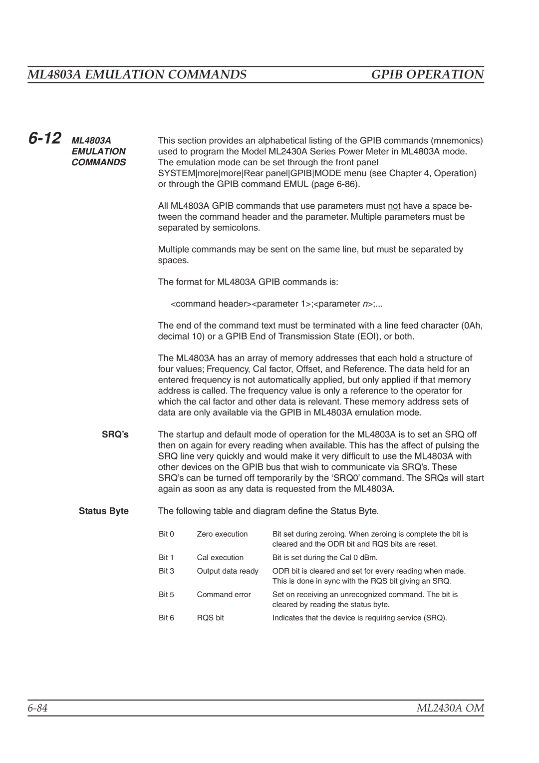
Status Byte | The following table and diagram define the Status Byte. | ||
| Bit 0 | Zero execution | Bit set during zeroing. When zeroing is complete the bit is |
|
|
| cleared and the ODR bit and RQS bits are reset. |
| Bit 1 | Cal execution | Bit is set during the Cal 0 dBm. |
| Bit 3 | Output data ready | ODR bit is cleared and set for every reading when made. |
|
|
| This is done in sync with the RQS bit giving an SRQ. |
| Bit 5 | Command error | Set on receiving an unrecognized command. The bit is |
|
|
| cleared by reading the status byte. |
| Bit 6 | RQS bit | Indicates that the device is requiring service (SRQ). |
ML2430A OM | |
|
|
