Literature Number SPRU629 April
Important Notice
Read This First
Trademarks
Contents
Video Capture Port
Discusses operation of the video capture port
VCASTOP2, VCBSTOP2
VCASTRT1, VCBSTRT1
VCASTOP1, VCBSTOP1
VCASTRT2, VCBSTRT2
11.1
General Purpose I/O Operation
VDVSYNE2
Vcxo Interpolated Control Port
Figures
Xii
Figures Xiii
Video Port
Tables
Xvi
Tables Xvii
Topic
Overview
Video Port
SPRU629
Channel B
VCLK1 VCLK2 VCTL1 VCTL2
VCTL3
Channel a
DMA Interface
Video Port Fifo
Ysrca Cbsrca Crsrca Ysrcb Cbsrcb Crsrcb
Video Capture Fifo Configurations
Ysrca
Ysrca Cbsrca Crsrca
Y/C Video Capture Fifo Configuration
Ydsta Cbdst Crdst
Video Display Fifo Configurations
10-Bit Raw Video Display Fifo Configuration
Ydstb
Ydsta
Video Port Registers
10. Y/C Video Display Fifo Configuration
Video Port Pin Mapping
Video Capture Signal Mapping
Usage Raw Data Display Mode
Video Display Signal Mapping
Vdin Data Bus Usage for Capture Modes
Capture Mode BT.656 Raw Data
Data Bus 10-Bit 16-Bit 20-Bit Mode
Vdin Bus Usage for Capture Modes
Vdout Data Bus Usage for Display Modes
Vdout Data Bus Usage for Display Modes
Video Port
Peripheral Bus Reset
Reset Operation
Power-On Reset
Capture Channel Reset
Software Port Reset
Display Channel Reset
Interrupt Operation
Capture DMA Event Generation
DMA Operation
Fifo ≥
Capture DMA Event Generation Flow Diagram
Display DMA Event Generation
Display DMA Event Generation Flow Diagram
DMA Size and Threshold Restrictions
DMA Interface Operation
Data Bus Width
Clocks
Video Port Functionality Subsets
Video Port Functional Clocks
Video Capture Throughput
Video Port Throughput and Latency
Fifo Size
Bit Bit Dense 10-Bit
Y/C Video Capture Fifo Capacity
Bit Bit Dense 10/16-Bit 20-Bit Samples 5120 3840 2560 1280
Video Display Throughput
Raw Video Display Fifo Capacity
Acronym Register Name Section
Video Port Control Registers
Video Port Control Registers
Value Description
Video Port Control Register Vpctl
Video Port Control Register Vpctl Field Descriptions
Bit
None Activelow
None Clear
VCLK2P
None Reverse
Vpctl Bit
Video Port Operating Mode Selection
Operating Mode
Video Port Status Register Vpstat Field Descriptions
Video Port Status Register Vpstat
Video Port Interrupt Enable Register Vpie
Dcna
Serrb
Ccmpb
Lfda
Lfda Sfda VINTA2 VINTA1 Serra Ccmpa Covra
Video Port Interrupt Status Register Vpis
Dcna Dcmp
Tick STC
Vcount = Ystop
Vcbctl
Out of the port. The DMA complete interrupt can be used to
BT.656 or Y/C capture mode Lfda is set when long field
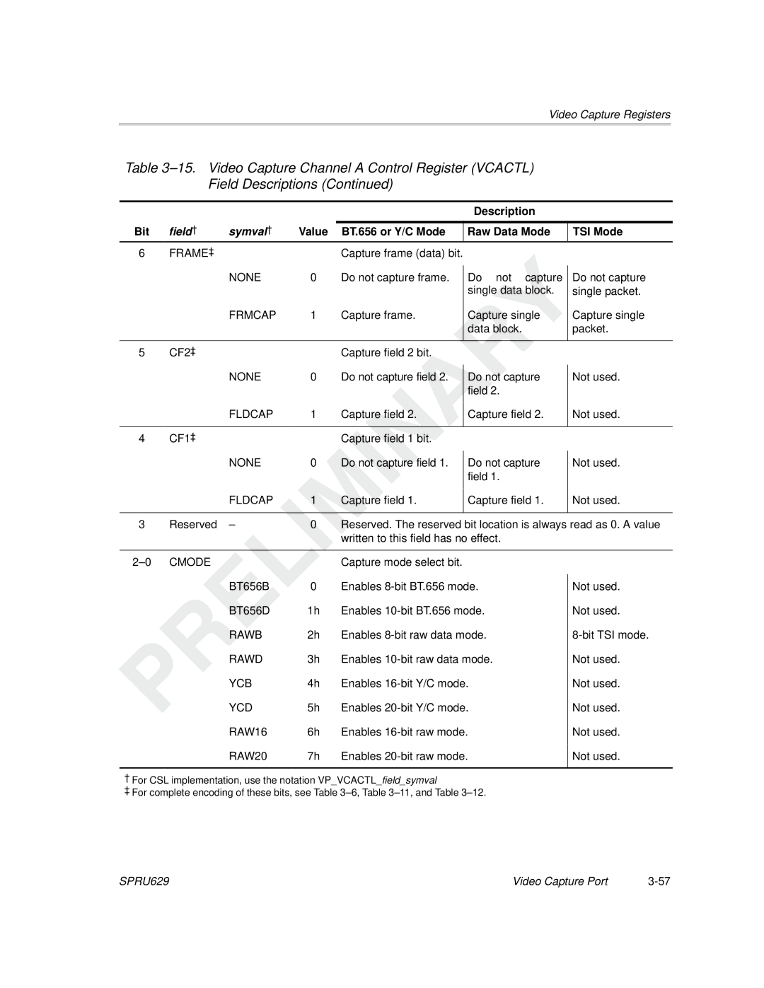
Vcactl
Video Capture Port
TSI Bit Cmode Bits Mode Description
Video Capture Mode Selection
Video Capture Mode Selection
1 BT.656 Capture Channels
BT.656 Video Capture Mode
BT.656 Video Timing Reference Codes
2 BT.656 Timing Reference Codes
Received F, V, and H Bits
Error Correction by Protection Bits
BT.656 Protection Bits
Line Information Bits Protection Bits
P 0 Bits
3 BT.656 Image Window and Capture
010 011 100 101
Common Video Source Parameters
Video Capture Parameters
4 BT.656 Data Sampling
Bit BT.656 Fifo Packing
5 BT.656 Fifo Packing
VDIN9-0 / VDIN19-10 Cb Cr 0 Y Cb 1 Y
Bit BT.656 Dense Fifo Packing
2 Y/C Timing Reference Codes
Y/C Video Capture Mode
1 Y/C Capture Channels
3 Y/C Image Window and Capture
Bit Y/C Fifo Packing
4 Y/C Fifo Packing
VDIN9-0 VDIN19-10 Little-Endian Packing Big-Endian Packing
Bit Y/C Dense Fifo Packing
Capture Determination and Notification
BT.656 and Y/C Mode Field and Frame Operation
Operation
BT.656 and Y/C Mode Capture Operation
VC xCTL Bit
VCxCTL Bit
Vertical Synchronization
VC xCTL Bit VMode
Vertical Counter Reset Point
Vertical Synchronization Programming
Vcount Operation Example EXC =
VCxCTL Bit HMode
Horizontal Counter Reset Point
Horizontal Synchronization
Horizontal Synchronization Programming
Hcount Operation Example EXC =
EAV code
Field Identification
Field Identification Programming
Field Detect Method
Short and Long Field Detect
11.Field 1 Detection Timing
Filter Operation
10. Input Filter Mode Selection
Video Input Filtering
Input Filter Modes
Scaling Operation
Chrominance Resampling Operation
13 /2 Scaled Co-Sited Filtering
EAV
Edge Pixel Replication
SAV
Xstart Xsize SAV
16. Capture Window Not Requiring Edge Pixel Replication
Vertical Ancillary Vanc Data Capture
Ancillary Data Capture
Horizontal Ancillary Hanc Data Capture
Raw Data Capture Notification
Raw Data Capture Mode
Raw Data Fifo Packing
11. Raw Data Mode Capture Operation
17 -Bit Raw Data Fifo Packing
19 -Bit Dense Raw Data Fifo Packing
21 -Bit Raw Data Fifo Packing
TSI Data Capture
TSI Capture Mode
TSI Capture Features
Vclkin Capen Pacstrt
TSI Capture Error Detection
Synchronizing the System Clock
Ctmode
PCR
Vcactl Bit
12. TSI Capture Mode Operation
TSI Data Capture Notification
Perr
Writing to the Fifo
Vclkin
TSI TSI Fifo
Reading from the Fifo
Capture Line Boundary Conditions
Fifo
Ipcount = IMGHSIZE78 Vclkout
Capturing Video in BT.656 or Y/C Mode
Handling Fifo Overrun in BT.656 or Y/C Mode
Capturing Video in Raw Data Mode
Handling Fifo Overrun Condition in Raw Data Mode
Capturing Data in TSI Capture Mode
Handling Fifo Overrun Condition in TSI Capture Mode
13. Video Capture Control Registers
Video Capture Registers
Video Capture Channel x Status Register VCASTAT, Vcbstat
Description Bit
BT.656 or Y/C Mode Raw Data Mode TSI Mode
Detected
Value BT.656 or Y/C Mode Raw Data Mode TSI Mode
Vcfld
Video Capture Channel a Control Register Vcactl
FIELD2
Block
Rdfe
FIELD1
V0EAV
Eavfid
FDL
V1EAV
CON ‡
Half
Description Raw Data Mode TSI Mode
VCXSTART/VCVBLNKP
Vcystart
SSE
Vcvblnkp
Vcxstart
Vcxstop
Vcystop
Field† Symval†
FFFh Last captured line Not used
VINT1
VIF2 FSCL2
VINT2
VIF1
VIF2
SPRU629
VCTHRLD1
VCTHRLD2
CAPEVTCT1
CAPEVTCT2
CON Frame CF2 CF1
Video Capture Channel B Control Register Vcbctl
Vrst Hrst Vcen PK10B Lfde Sfde Resmpl
F1C, F2C, and Frmc status bits, in VCBSTAT, are not
EAV or Not used VCTL1 active edge
Capture field Not used
CON‡
Enstc Tcken Sten Ctmode
TSI Capture Control Register Tsictl
24. TSI Capture Control Register Tsictl Field Descriptions
Value BT.656, Y/C Mode TSI Mode Or Raw Data Mode
Bit Field
BT.656, Y/C Mode TSI Mode Or Raw Data Mode
TSI Clock Initialization LSB Register Tsiclkinitl
Inpcr
Inpcre
TSI Clock Initialization MSB Register Tsiclkinitm
Inpcrm
42. TSI System Time Clock LSB Register Tsistclkl
TSI System Time Clock LSB Register Tsistclkl
Pcre
TSI System Time Clock MSB Register Tsistclkm
Pcre Pcrm
ATC
TSI System Time Clock Compare LSB Register Tsistcmpl
45. TSI System Time Clock Compare MSB Register Tsistcmpm
TSI System Time Clock Compare MSB Register Tsistcmpm
Atcm
TSI System Time Clock Compare Mask LSB Register Tsistmskl
TSI System Time Clock Compare Mask MSB Register Tsistmskm
Tickct
TSI System Time Clock Ticks Interrupt Register Tsiticks
35. Video Capture Fifo Registers Function
Capture Mode Register BT.656 or Y/C Raw Data
Video Capture Fifo Registers
34. Video Capture Fifo Registers
Video Display Port
Image Timing
Video Display Mode Selection
Video Display Mode Selection
Dmode Bits Mode Description
Ntsc Compatible Interlaced Display
Interlaced Blanking Intervals and Video Areas
Video Display Counters
Progressive Blanking Intervals and Video Area
Fpcount
Horizontal Blanking and Horizontal Sync Timing
Vsync
Sync Signal Generation
Flcount
Vblnk
Port Sync Operation
External Sync Operation
Display Timing Reference Codes
BT.656 Video Display Mode
Line Number
BT.656 Frame Timing
11.Digital Vertical F and V Transitions
3 BT.656 Image Display
Blanking Codes
12 -Bit BT.656 Fifo Unpacking
4 BT.656 Fifo Unpacking
13 -Bit BT.656 Fifo Unpacking
14. BT.656 Dense Fifo Unpacking
1 Y/C Display Timing Reference Codes
Y/C Video Display Mode
4 Y/C Fifo Unpacking
2 Y/C Blanking Codes
3 Y/C Image Display
16 -Bit Y/C Fifo Unpacking
17 -Bit Y/C Fifo Unpacking
18 -Bit Y/C Dense Fifo Unpacking
Vdctl Bit
Output Filter Mode Selection
Video Output Filtering
Output Filter Modes
19. Chrominance Resampling
20 x Co-Sited Scaling
23. Luma Edge Replication
Vertical Ancillary Vanc Data Display
Raw Data Display Mode
Ancillary Data Display
Horizontal Ancillary Hanc Data Display
Raw Data Fifo Unpacking
Raw Mode RGB Output Support
26 -Bit Raw Fifo Unpacking
28 -Bit Raw Fifo Unpacking
30 -Bit Raw 3/4 Fifo Unpacking
Display Determination and Notification
Video Display Field and Frame Operation
CON Frame DF2 DF1
Display Operation
Video Display Event Generation
Display Line Boundary Conditions
32. Display Line Boundary Example
Interlaced BT.656 Timing Example
Display Timing Examples
33. BT.656 Interlaced Display Horizontal Timing Example
SPRU629
34. BT.656 Interlaced Display Vertical Timing Example
Interlaced Raw Display Example
35. Raw Interlaced Display Horizontal Timing
SPRU629
36. Raw Interlaced Display Vertical Timing Example
3 Y/C Progressive Display Example
37. Y/C Progressive Display Horizontal Timing Example
SPRU629
38. Y/C Progressive Display Vertical Timing Example
Displaying Video in BT.656 or Y/C Mode
Displaying Video in BT.656 or Y/C Mode
Displaying Video in Raw Data Mode
Displaying Video in Raw Data Mode
Handling Underrun Condition of the Display Fifo
Video Display Control Registers
Video Display Registers
Video Display Status Register Vdstat
Video Display Status Register Vdstat Field Descriptions
Video Display Control Register Vdctl Field Descriptions
BT.656 and Y/C Mode Raw Data Mode
Video Display Control Register Vdctl
Output
Disable Enable
Blkdis
FXS
Value BT.656 and Y/C Mode Raw Data Mode
Blanking
Rgbx
Flddis
Frmdis
Frmwidth
Video Display Frame Size Register Vdfrmsz
Frmheight
Hbdla
Video Display Horizontal Blanking Register Vdhblnk
Hblnkstart
Delay
Hblnkstop
VBLNKXSTART1
VBLNKYSTART1
VBLNKXSTOP1
VBLNKYSTOP1
Field† Symval†
VBLNKXSTART2
VBLNKYSTART2
VBLNKXSTOP2
VBLNKYSTOP2
Video Display Field 1 Image Offset Register VDIMGOFF1
Negoff
IMGVOFF1
IMGHOFF1
IMGHSIZE1
Video Display Field 1 Image Size Register VDIMGSZ1
IMGVSIZE1
IMGHOFF2
Video Display Field 2 Image Offset Register VDIMGOFF2
IMGVOFF2
None
IMGHSIZE2
Video Display Field 2 Image Size Register VDIMGSZ2
IMGVSIZE2
FLD1XSTART
Video Display Field 1 Timing Register VDFLDT1
FLD1YSTART
FLD2XSTART
Video Display Field 2 Timing Register VDFLDT2
FLD2YSTART
Incpix
Video Display Threshold Register Vdthrld
VDTHRLD1
VDTHRLD2
Hsyncstart
Video Display Horizontal Synchronization Register Vdhsync
Hsyncstop
VSYNCXSTART1
VSYNCYSTART1
VSYNCXSTOP1
VSYNCYSTOP1
VSYNCXSTART2
VSYNCYSTART2
VSYNCXSTOP2
VSYNCYSTOP2
Crld
Video Display Counter Reload Register Vdreload
Vrld
Hrld
DISPEVT1
Video Display Display Event Register Vddispevt
DISPEVT2
Clipclow
Video Display Clipping Register Vdclip
Clipchigh
Clipyhigh Clipylow
Ydefval
Video Display Default Display Value Register Vddefval
Crdefval Cbdefval
Crdefval
Defval
64. Video Display Vertical Interrupt Register Vdvint
Video Display Vertical Interrupt Register Vdvint
Fbitclr
Video Display Field Bit Register Vdfbit
Fbitset
VBITSET1
VBITCLR1
Field† Symval†
VBITSET2
VBITCLR2
Field† Symval†
Register Field 525/60 Value 625/50 Value
Video Display Registers Recommended Values
34. Video Display Register Recommended Values
VDVBIT1 VBITSET1
VDVSYNS2 VSYNCXSTART2
VDVSYNE2 VSYNCXSTOP2
Vdfbit Fbitclr Fbitset
Register BT.656 or Y/C Raw Data
Video Display Fifo Registers
35. Video Display Fifo Registers
36. Video Display Fifo Registers Function
Gpio Registers
General Purpose I/O Operation
Video Port Registers
Gpio Registers
Class
Video Port Peripheral Identification Register Vppid
Type
Class Revision
Soft Free
Video Port Peripheral Control Register PCR
Comp
Peren
Soft
Stop
Normal
Video Port Pin Function Register Pfunc
Video Port Pin Function Register Pfunc Field Descriptions
PFUNC22
PFUNC0
PFUNC20
PFUNC10
VDATA10TO19
VCTL3IN
Video Port Pin Direction Register Pdir
Video Port Pin Direction Register Pdir Field Descriptions
PDIR22
PDIR20
PDIR21
VCTL2IN
VCTL2OUT
PDIR4
PDIR8
VDATA8TO9IN
VDATA8TO9OUT
PDIN7 PDIN6
Video Port Pin Data Input Register Pdin
PDIN20
PDIN12
Video Port Pin Data Input Register Pdin Field Descriptions
Video Port Pin Data Output Register Pdout
PDOUT20
Video Port Pin Data Out Register Pdout Field Descriptions
PDOUT21
Video Port Pin Data Set Register Pdset
PDSET20
Video Port Pin Data Set Register Pdset Field Descriptions
PDSET21
Video Port Pin Data Clear Register Pdclr
Video Port Pin Data Clear Register Pdclr
Video Port Pin Data Clear Register Pdclr Field Descriptions
Video Port Pin Interrupt Enable Register Pien
Video Port Pin Interrupt Enable Register Pien
PIEN20
PIEN21
PIPOL13 PIPOL12
Video Port Pin Interrupt Polarity Register Pipol
PIPOL21 PIPOL20 PIPOL19
PIPOL17 PIPOL16 PIPOL15
PIPOL21
PIPOL22
VCTL3ACTHI
VCTL3ACTLO
Video Port Pin Interrupt Status Register Pistat
PISTAT20
PISTAT22
VCTL3INT
VCTL2INT
PICLR4
Video Port Pin Interrupt Clear Register Piclr
PICLR20
PICLR22
PICLR21
Vcxo Interpolated Control Port
Overview
Operational Details
VIC Port Interface Signals
VIC Port Signal Direction Description
Interface
Example Values for Interpolation Rate
VIC Port Registers
Enabling VIC Port
VIC Port Registers
VIC Control Register Vicctl Field Descriptions
VIC Control Register Vicctl
GO bit can be written to at any time
Vicinbits
VIC Input Register Vicin
VIC Input Register Vicin Field Descriptions
Vicclkdiv
VIC Clock Divider Register Vicdiv
VIC Clock Divider Register Vicdiv Field Descriptions
Video Port Configuration Examples
VCAIMGHSIZE2 * VCAIMGVSIZE2
Example 1 Noncontinuous Frame Capture for 525/60 Format
Frame
VPVCASTOP1RMKVCAYSTOP1, VCAXSTOP1
VPVCASTRT1SSEENABLE, VCAXSTART1
Vpvcactlblkcapclear
SPRU629
Vcayedmafrmcnt
Edmaoptrmk Edmaoptprimedium
Vdhblnkstop Vdhblnkstart +
Example 2 Noncontinuous Frame Display for 525/60 Format
Define vertical blanking bitVDVBITn reg values
VDIMGHSIZE1 * VDIMGVSIZE1
Dmode
VPVDFRMSZRMKVDFRMHEIGHT, Vdfrmwidth
VPVDVBLKS2RMKVDVBLNKYSTART2, VDVBLNKXSTART2
VPVDVSYNE2RMKVDVSYNCYSTOP2, VDVSYNCXSTOP2
Vpvdstatfrmdclear
Vdyedmafrmcnt Vdyedmaelecnt
Example 2 Noncontinuous Frame Display for 525/60 Format
EDMAOPT2DSYES
Index
Index-2
Index-3
Pin data set register Pdset Pin direction register Pdir
Vcaevtct
Vdhblnk
Index-7
Vddefval Vddispevt
Index-9
Ydsta Ydstb