Intel PXA255 Processor
Intel PXA255 Processor Developer’s Manual
Contents
Power Manager General Configuration Register Pcfr
Contents
Expansion Card Interface Timing Diagrams and Parameters
DMA
10-1
11-1
12.6
14.3
15.5
Figures
BitBurst-of-Eight ROM or Flash Read Timing Diagram MSC0RDF =
10-25
Tables
Clocks Manager Register Summary
Sxcnfg
10-6
10-8
12-26
15-7
Revision History
Date Revision Description
Xxiv
Intel XScale Microarchitecture Features
System Integration Features
Clocks and Power Controllers
Memory Controller
Universal Serial Bus USB Client
6 AC97 Controller
DMA Controller Dmac
LCD Controller
Inter-IC Sound I2S Controller
Gpio
Synchronous Serial Protocol Controller Sspc
Inter-Integrated Circuit I2C Bus Interface Unit
UARTs
Pulse-Width Modulator PWM
OS Timers
Real-Time Clock RTC
Interrupt Control
Introduction
System Architecture
Overview
Intel XScale Microarchitecture Implementation Options
Coprocessor 7 Register 4 Psfs Bit
Coprocessor 14 Registers 0-3 Performance Monitoring
Coprocessor 14 Register 6 and 7- Clock and Power Management
CPU Core Fault Register Bit Definitions
Coprocessor 15 Register 0 ID Register Definition
PXA255 Processor ID Values
Coprocessor 15 Register 1 P-Bit
ID Bit Definitions
ARM ID Jtag ID
I/O Ordering
Semaphores
Interrupts
USB
Reset
Unit Sleep Mode Gpio Reset Watchdog Reset Hard Reset
ICP
Internal Registers
Selecting Peripherals vs. General Purpose I/O
Pin List
Power on Reset and Boot Operation
Power Management
Processor Pin Types
Pin & Signal Descriptions for the PXA255 Processor Sheet 1
Pin Name Type Signal Descriptions Reset State Sleep State
Pin & Signal Descriptions for the PXA255 Processor Sheet 2
Pin & Signal Descriptions for the PXA255 Processor Sheet 3
Psktsel
Pin & Signal Descriptions for the PXA255 Processor Sheet 4
Pin & Signal Descriptions for the PXA255 Processor Sheet 5
Pin & Signal Descriptions for the PXA255 Processor Sheet 6
Pin & Signal Descriptions for the PXA255 Processor Sheet 7
Rtcclk Icocz
Pin & Signal Descriptions for the PXA255 Processor Sheet 8
Bootsel
Pwren
Pin & Signal Descriptions for the PXA255 Processor Sheet 9
Pin Description Notes Sheet 1
Memory Map
Pin Description Notes Sheet 2
Memory Map Part One From 0x80000000 to 0xFFFF Ffff
Memory Map Part Two From 0x00000000 to 0x7FFF Ffff
Unit Address Register Symbol Register Description
System Architecture Register Summary
System Architecture Register Address Summary Sheet 1
System Architecture Register Address Summary Sheet 2
System Architecture Register Address Summary Sheet 3
System Architecture Register Address Summary Sheet 4
System Architecture Register Address Summary Sheet 5
Unit
System Architecture Register Address Summary Sheet 6
System Architecture Register Address Summary Sheet 7
Unit Address
System Architecture Register Address Summary Sheet 8
System Architecture Register Address Summary Sheet 9
System Architecture Register Address Summary Sheet 10
System Architecture Register Address Summary Sheet 11
System Architecture Register Address Summary Sheet 12
Clocks and Power Manager
Clock Manager Introduction
Power Manager Introduction
Clock Manager
OST
Retains Power in Sleep
PWM SSP
Ficp I2C MMC
Core Phase Locked Loop
1 32.768 kHz Oscillator
2 3.6864 MHz Oscillator
Core PLL Output Frequencies for 3.6864 MHz Crystal
4 95.85 MHz Peripheral Phase Locked Loop
5 147.46 MHz Peripheral Phase Locked Loop
Sdram
Resets and Power Modes
Hardware Reset
Clock Gating
Watchdog Reset
Invoking Gpio Reset
Gpio Reset
Completing a Watchdog Reset
Behavior During Gpio Reset
Completing Gpio Reset
Run Mode
Turbo Mode
Entering Turbo Mode
Exiting Turbo Mode
Idle Mode
Behavior in Turbo Mode
Entering Idle Mode
Frequency Change Sequence
Behavior in Idle Mode
Exiting Idle Mode
Preparing for a Frequency Change Sequence
Invoking the Frequency Change Sequence
Behavior During the Frequency Change Sequence
8 33-MHz Idle Mode
Completing the Frequency Change Sequence
Entering 33-MHz Idle Mode
Behavior in 33-MHz Idle Mode
Sleep Mode
Exiting 33-MHz Idle Mode
Sleep Mode External Voltage Regulator Requirements
Preparing for Sleep Mode
Entering Sleep Mode
Clocks and Power Manager
Behavior in Sleep Mode
Exiting Sleep Mode
Clocks and Power Manager
Power Mode Exit Sequence Table Sheet 1
Power Mode Summary
Power Mode Entry Sequence Table
Idle
Power Mode Exit Sequence Table Sheet 2
Power Manager Registers
Power Mode Supply Source Module Turbo Run
Pmcr
Power Manager Control Register Pmcr
Pmcr Bit Definitions
Idae
Pcfr
Power Manager General Configuration Register Pcfr
Pcfr Bit Definitions
Opde
Wertc
Power Manager Wake-Up Enable Register Pwer
Pwer Bit Definitions
Pwer
0x40F00010
Power Manager Rising-Edge Detect Enable Register Prer
10. Prer Bit Definitions
Prer
0x40F00014
Power Manager Falling-Edge Detect Enable Register Pfer
11. Pfer Bit Definitions
Pfer
0x40F00018
Power Manager Gpio Edge Detect Status Register Pedr
12. Pedr Bit Definitions
Pedr
Pssr
Power Manager Sleep Status Register Pssr
13. Pssr Bit Definitions Sheet 1
RDH
14. Pspr Bit Definitions
Power Manager Scratch Pad Register Pspr
13. Pssr Bit Definitions Sheet 2
CPU VFS
Power Manager Fast Sleep Walk-up Configuration Register Pmfw
15. Pmfw Register Bitmap and Bit Definitions
PGSR0
16. PGSR0 Bit Definitions
17. PGSR1 Bit Definitions
SS9 SS8 SS7 SS6 SS5 SS4 SS3 SS2 SS1 SS0
18. PGSR2 Bit Definitions
Reset Controller Status Register Rcsr
Bit Reset 0x40F00028
PGSR2
19. Rcsr Bit Definitions
Core Clock Configuration Register Cccr
Clocks Manager Registers
Rcsr
Bit Reserved
20. Cccr Bit Definitions
0x41300000
Multiplier =
Clock Enable Register Cken
21. Cken Bit Definitions Sheet 1
CKEN8
Description I2S Unit Clock Enable
21. Cken Bit Definitions Sheet 2
CKEN5
Coprocessor 14 Clock and Power Management
Oscillator Configuration Register Oscc
22. Oscc Bit Definitions
Core Clock Configuration Register Cclkcfg
23. Coprocessor 14 Clock and Power Management Summary
24. Cclkcfg Bit Definitions
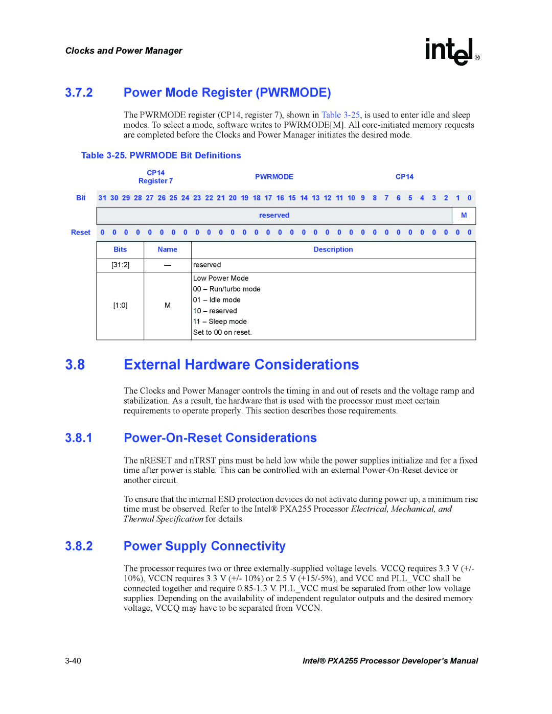
Power Supply Connectivity
Power Mode Register Pwrmode
Power-On-Reset Considerations
External Hardware Considerations
Power Manager Register Summary
Clocks and Power Manager Register Summary
Driving the Crystal Pins from an External Clock Source
Clocks Manager Register Locations
27. Power Manager Register Summary
General-Purpose I/O
Gpio Operation
General-Purpose I/O Block Diagram
Gpio Alternate Functions
Gpio Alternate Functions Sheet 1
Gpio Alternate Functions Sheet 2
Gpio Alternate Functions Sheet 3
MMCCS0 ALTFN1OUT
Mbgnt ALTFN1OUT
Gpio Register Definitions
Gpio Alternate Functions Sheet 4
Gpio Register Definitions Sheet 1
GPLR0 Bit Definitions
Gpio Pin-Level Registers GPLR0, GPLR1, GPLR2
Gpio Register Definitions Sheet 2
GPLR0
GPLR2 Bit Definitions
Gpio Pin Direction Registers GPDR0, GPDR1, GPDR2
GPLR1 Bit Definitions
GPLR1
GPDR0 Bit Definitions
GPDR1 Bit Definitions
GPDR2 Bit Definitions
GPSR0
GPSR0 Bit Definitions
10. GPSR1 Bit Definitions
PS9 PS8 PS7 PS6 PS5 PS4 PS3 PS2 PS1 PS0
11. GPSR2 Bit Definitions
12. GPCR0 Bit Definitions
13. GPCR1 Bit Definitions
GPCR2 Bit Definitions
GPCR2
15. GRER0 Bit Definitions
16. GRER1 Bit Definitions
17. GRER2 Bit Definitions
18. GFER0 Bit Definitions
19. GFER1 Bit Definitions
GFER2 Bit Definitions
Gpio Edge Detect Status Register GEDR0, GEDR1, GEDR2
21. GEDR0 Bit Definitions
22. GEDR1 Bit Definitions
GEDR2 Bit Definitions
GEDR2
GAFR0L
24. GAFR0L Bit Definitions
25. GAFR0U Bit Definitions
AF9 AF8 AF7 AF6 AF5 AF4 AF3 AF2 AF1 AF0
GAFR1L
26. GAFR1L Bit Definitions
27. GAFR1U Bit Definitions
GAFR1U
GAFR2L
28. GAFR2L Bit Definitions
29. GAFR2U Bit Definitions
GAFR2U
Interrupt Controller
Interrupt Controller Operation
Interrupt Controller Block Diagram
Interrupt Controller Register Definitions
30. Icmr Bit Definitions
Interrupt Controller Mask Register Icmr
Interrupt Controller Level Register Iclr
Icmr
Interrupt Controller Control Register Iccr
31. Iclr Bit Definitions
32. Iccr Bit Definitions
33. Icip Bit Definitions
34. Icfp Bit Definitions
Icpr
Interrupt Controller Pending Register Icpr
35. Icpr Bit Definitions Sheet 1
IS9 IS8
IS14 IS13 IS12 IS11 IS10
Network SSP Service Request Interrupt Pending
35. Icpr Bit Definitions Sheet 2
IS16
System Integration Unit
35. Icpr Bit Definitions Sheet 3
36. List of First-Level Interrupts Sheet 1
Bit Position Source Unit
Real-Time Clock RTC
Real-Time Clock Operation
36. List of First-Level Interrupts Sheet 2
RTC Register Definitions
RTC Trim Register Rttr
RTC Alarm Register Rtar
Rttr Bit Definitions
38. Rtar Bit Definitions
39. Rcnr Bit Definitions
RTC Counter Register Rcnr
RTC Status Register Rtsr
Rcnr
Trim Procedure
Oscillator Frequency Calibration
40. Rtsr Bit Definitions
Rttr Value Calculations
Trim Example #1 Measured Value Has No Fractional Component
Trim Example #2 Measured Value Has a Fractional Component
Operating System OS Timer
Maximum Error Calculation Versus RTC Accuracy
Watchdog Timer Operation
OS Timer Register Definitions
OS Timer Match Register 0-3 OSMRx
42. Oier Bit Definitions
OS Timer Interrupt Enable Register Oier
41. OSMRx Bit Definitions
OSMR3, OSMR2, OSMR1
OS Timer Status Register Ossr
OS Timer Watchdog Match Enable Register Ower
OS Timer Count Register Oscr
43. Ower Bit Definitions
Pulse Width Modulator Operation
0x40A00014 Bit Reset ? ? ? ? ? ? ? ? Bits
Pulse Width Modulator
Ossr Bit Definitions
PWMn Block Diagram
1.1 Interdependencies
Register Descriptions
Reset Sequence
Power Management Requirements
PWM Control Registers PWMCTRLn
0x40B00000
PWM Duty Cycle Registers PWMDUTYn
46. PWMCTRLn Bit Definitions
Prescale
PWMDUTY0, PWMDUTY1
PWM Period Control Register PWMPERVALn
47. PWMDUTYn Bit Definitions
Fdcycle Dcycle
Pulse Width Modulator Output Wave Example
48. PWMPERVALn Bit Definitions
0x40B00008
System Integration Unit Register Summary
Gpio Register Locations
49. Gpio Register Addresses Sheet 1
OS Timer Register Locations
Interrupt Controller Register Locations
Real-Time Clock Register Locations
52. OS Timer Register Addresses Sheet 2
Pulse Width Modulator Register Locations
53. Pulse Width Modulator Register Addresses
Dmac Block Diagram
DMA Description
Dmac Signal List
Signal Descriptions
DREQ10 and PREQ370 Signals
Signal Signal Type To/From Definition In/Out
Dmairq Signal
DMA Channel Priority Scheme
Channel Priority if all channels are running concurrently
Channel Priority
Priority Schemes Examples
No-Descriptor Fetch Mode
DMA Descriptors
DMA Channel Priority
Descriptor Fetch Mode
No-Descriptor Fetch Mode Channel State
DMA Controller
Channel States
Servicing an Interrupt
Read and Write Order
Byte Transfer Order
Trailing Bytes
Little Endian Transfers
Transferring Data
Servicing Internal Peripherals
Dcmdincsrcaddr = Dcmdflowsrc = Dcmdflowtrg =
Dcmd
Quick Reference for DMA Programming
DMA Quick Reference for Internal Peripherals Sheet 1
Drcmr
Unit Function Fifo Address Width
Servicing Companion Chips and External Peripherals
DMA Quick Reference for Internal Peripherals Sheet 2
Burst Size Source
DMA Controller
Memory-to-Memory Moves
DMA Channel Control/Status Register DCSRx
Dmac Registers
DMA Interrupt Register Dint
Dint Bit Definitions
Reqpend
DCSRx Bit Definitions Sheet 1
RUN
Stopstate Endintr Startintr Buserrintr
Reset 0 0 0 0 0 0 0 0 0 0 0 0 0 0 0 0 0 0 0 0 0 0 0 0 0 0 0
DCSRx Bit Definitions Sheet 2
DRCMRx Bit Definitions
DMA Request to Channel Map Registers DRCMRx
DMA Descriptor Address Registers DDADRx
Chlnum
Descriptor Address
DMA Source Address Registers
DDADRx Bit Definitions
Stop
Source Address
DMA Target Address Registers DTADRx
10. DSADRx Bit Definitions
Srcaddr
Target Address
DMA Command Registers DCMDx
11. DTADRx Bit Definitions
Trgaddr
Endian Width
12. DCMDx Bit Definitions Sheet 1
Incsrcaddr
Size
Width
12. DCMDx Bit Definitions Sheet 2
Endian
Length
Example 1. How to set up and start a channel
Examples
Struct longddadr longdsadr longdtadr shortlength shortdcmd
DMA Controller Register Summary
13. DMA Controller Register Summary Sheet 1
13. DMA Controller Register Summary Sheet 2
13. DMA Controller Register Summary Sheet 3
13. DMA Controller Register Summary Sheet 4
13. DMA Controller Register Summary Sheet 5
Memory Controller
Functional Description
Sdram Interface Overview
Static Memory Interface / Variable Latency I/O Interface
Memory System Examples
3 16-Bit PC Card / Compact Flash Interface
Sdram Memory System Example
Static Memory System Example
Bus Operation Burst Size
Memory Accesses
Device Transactions
Words Bits
Aborts and Nonexistent Memory
Synchronous Dram Memory Interface
Reads and Writes
Sdram Mdcnfg Register Mdcnfg
Mdcnfg Bit Definitions Sheet 1
Mdcnfg Bit Definitions Sheet 2
DADDR2
Mdcnfg Bit Definitions Sheet 3
DNB2
DLATCH2
Sdram Mode Register Set Configuration Register Mdmrs
Mdmrs Bit Definitions Sheet 1
Low-Power Sdram Mode Register Set Configuration Register
Mdmrs Bit Definitions Sheet 2
0X4800
Sdram Mdrefr Register Mdrefr
Mdmrslp Register Bit Definitions
Mdmrslp
APD K2DB2 K2RUN K1DB2 K1RUN E1PIN K0DB2 K0RUN E0PIN
Mdrefr Bit Definitions Sheet 1
Mdrefr
DRI
Mdrefr Bit Definitions Sheet 2
0 1 0 0 1 * * 1
1 1 1 1 1 1 1
Fixed-Delay or Return-Clock Data Latching
Mdrefr Bit Definitions Sheet 3
APD
Sample Sdram Memory Size Options
Sdram Memory Options
Sdram Addressing Modes
Number Chips Partition Size
# Bits
‘0’
1x12x8x32 ‘0’ 1x12x8x16 1x12x9x32 1x12x9x16 1x12x10x32
MA2410
Col Data
2x13x10x16 ‘0’
# Bits External Address pins at Sdram RAS Time
Not Valid illegal addressing combination
BA0
MA24 MA23
MA20
A10
MA24
BA1 BA0
A11 A10
Memory Controller
Sdram Command Overview
A12
11. Sdram Command Encoding
12. Sdram Mode Register Opcode Table
Sdram Waveforms
Sdclk
Data
SDRAMreadsamebankdiffrow
SDRAMwrite
SDCLK1 SDCKE1
Synchronous Static Memory Configuration Register Sxcnfg
Synchronous Static Memory Interface
Sxcnfg
13. Sxcnfg Bit Definitions Sheet 1
0x4800001C
SXLATCH2 SXTP2 SXCA2 SXRA2 SXRL2 SXCL2 SXEN2
SXRL2 SXCL2 SXEN2
Sxcnfg Bit Definitions Sheet 2
SXLATCH2
SXLATCH0
13. Sxcnfg Bit Definitions Sheet 3
SXCL0
Smrom Memory Options
Sxcnfg Bit Definitions Sheet 4
SXEN0
Smrom
Sxmrs
Synchronous Static Memory Timing Diagrams
16. Sxmrs Bit Definitions
SXMRS2
Non-SDRAM Timing Sxmem Operation
Sdclk Sdcke
17. Read Configuration Register Programming Values
Memclk SDCLK0 Mdrefr
Non-SDRAM Timing Flash Read Timing Diagram
12shows the burst-of-eight read timing diagram
4.2 K3 Synchronous StrataFlash Reset
Asynchronous Static Memory
Static Memory Interface
Sram
Data Size MA10 DQM30
19 -Bit Bus Write Access
20 -Bit Bus Write Access
Data Size MA0 DQM10
21 -Bit Byte Address Bits MA10 for Reads Based on DQM30
22 -Bit Byte Address Bit MA0 for Reads Based on DQM10
23. SA-1111 Register Bit Definitions
Asynchronous Static Memory Control Registers MSCx
MSC1
24. MSC0/1/2 Bit Definitions Sheet 1
MSC0
MSC2
RRR1/3/5 RDN1/3/5 Reset RDF1/3/5
Bits Access Name
24. MSC0/1/2 Bit Definitions Sheet 2
24. MSC0/1/2 Bit Definitions Sheet 3
Sram
NOE
ROM Interface
Timing Memory Clocks MSCxRTx Device
NWE NOE
ROM Timing Diagrams and Parameters
Clkmem
RDN+1
Sram Timing Diagrams and Parameters
Sram Interface Overview
20shows the timing for Sram writes
Variable Latency I/O Vlio Interface Overview
Variable Latency I/O Timing Diagrams and Parameters
RDF+1+Waits RRR*2+1
RDF+1+Waits
Flash Memory Timing Diagrams and Parameters
Flash Memory Interface
23. Asynchronous 32-Bit Flash Write Timing Diagram 2 Writes
CMD Data
26. MCMEM0/1 Bit Definitions
Expansion Memory Timing Configuration Register
16-Bit PC Card/Compact Flash Interface
MCMEM0
MCATT0
27. MCATT0/1 Bit Definitions
28. MCIO0/1 Bit Definitions
MCATT1
29. Card Interface Command Assertion Code Table
MCMEMxASST XASSTHOLD XASSTWAIT +
Mecr
Expansion Memory Configuration Register Mecr
30. Mecr Bit Definition
CIT NOS
3 16-Bit PC Card Overview
26 -Bit PC Card Memory Map
33. Attribute Memory Space Write Commands
31. Common Memory Space Write Commands
32. Common Memory Space Read Commands
34. Attribute Memory Space Read Commands
37 -Bit I/O Space Write Commands nIOIS16 =
38 -Bit I/O Space Read Commands nIOIS16 =
External Logic for 16-Bit PC Card Implementation
DIR
Socket
Expansion Card Interface Timing Diagrams and Parameters
29 -Bit PC Card Memory or I/O 16-Bit Half-word Access
30 -Bit PC Card I/O 16-Bit Access to 8-Bit Device
Companion Chip Interface
31. Alternate Bus Master Mode
32. Variable Latency IO
Alternate Bus Master Mode
Gpio Reset
NVDDFAULT/nBATTFAULT with Pmcridae Disabled
NVDDFAULT/nBATTFAULT with Pmcridae Enabled
Boot Time Defaults
Options and Settings for Boot Memory
Alternate Booting
Bootdef Read-Only Register Bootdef
Bootdef
40. Bootdef Bitmap
41. Valid Boot Configurations Based on Processor Type
PKG Type Boot SEL
Boot-Time Configurations
Sxcnfg
34. Smrom Boot Time Configurations and Register Defaults
Memory Interface Reset and Initialization
Smrom
Mdrefr 03CA 7FFF
Hardware, Watchdog, or Sleep Reset Operation
42. Memory Controller Pin Reset Values
Pin Name PXA255 Processor Reset Value
Memory Controller
Memory Controller Register Summary
Gpio Reset Procedure
Physical Address Symbol Register Name
43. Memory Controller Register Summary Sheet 1
43. Memory Controller Register Summary Sheet 2
LCD Controller
Features
LCD Controller
LCD Controller Block Diagram
Enabling the Controller
LCD Controller Operation
Pin Descriptions
Pin Descriptions
Disabling the Controller
Resetting the Controller
Detailed Module Descriptions
Input FIFOs
Lookup Palette
Temporal Modulated Energy Distribution Tmed Dithering
Compare Range for Tmed
Output FIFOs
LCD Controller Pin Usage
Passive Display Timing
Pixel Data Pins LDDx
6 DMA
Active Display Timing
LCD External Palette and Frame Buffers
External Palette Buffer
External Frame Buffer
Palette Buffer Format
Bits Per Pixel Data Memory Organization
10 Bits Per Pixel Data Memory Organization Passive Mode
Functional Timing
FrameBufferSize =
12. Passive Mode Start-of-Frame Timing
Vsync
Hsync Lbias
Register Descriptions
Lfclk Vsync Llclk Hsync Lbias
LCD Controller Control Register 0 LCCR0
LCD Controller
LDD
LCD Controller Data Pin Utilization Sheet 1
Single Passive Screen Portion Pins
LCD Controller Data Pin Utilization Sheet 2
LCCR0
Reset X X X X X X X X X X X
LCCR0 Bit Definitions Sheet 1
0x44000000 Bit Reserved
QDM DIS DPD
LCD Controller Control Register 1 LCCR1
LCCR0 Bit Definitions Sheet 2
PAS EFM IUM SFM LDM SDS CMS ENB
LCD Controller
BLW ELW HSW PPL
LCD Controller Control Register 2 LCCR2
LCCR1 Bit Definitions
BLW
LCD Controller
BFW EFW VSW LPP
LCD Controller Control Register 3 LCCR3
LCCR2 Bit Definitions
BFW
LCD Controller
LCD Controller
0x4400000C Bit Reserved
Reset X X X X 0 0 0
LCCR3 Bit Definitions Sheet 1
DPC BPP
Frame Descriptors
Reset X X X
LCD Controller DMA
LCCR3 Bit Definitions Sheet 2
FDADRx Bit Definitions
LCD DMA Frame Descriptor Address Registers FDADRx
LCD DMA Frame Source Address Registers FSADRx
FDADR0
LCD DMA Frame ID Registers FIDRx
FSADRx Bit Definitions
FIDRx Bit Definitions
LCD DMA Command Registers LDCMDx
LDCMD1
10. LDCMDx Bit Definitions
LDCMD0
PAL
Bint BRA
LCD DMA Frame Branch Registers FBRx
11. FBRx Bit Definitions
0 0 0 0 X X 0 Bits Name Description
LCD Controller Status Register Lcsr
LCD Controller
X X
0x44000038 Bit Reset X X
Lcsr Bit Definitions Sheet 1
EOF IUU IUL ABC BER SOF LDD
13. Liicr Bit Definitions
LCD Controller Interrupt ID Register Liidr
12. Lcsr Bit Definitions Sheet 2
Sint BS EOF QD OU IUU IUL ABC BER SOF LDD
TBS
Tmed RGB Seed Register Trgbr
14. Trgbr Bit Definitions
TRS
Tmed Control Register TCR
LCD Controller Register Summary
15. TCR Bit Definitions
16. LCD Controller Register Summary Sheet 1
16. LCD Controller Register Summary Sheet 2
LCD Controller
External Interface to Codec
Signal Description
External Interface to Synchronous Serial Peripherals
Name Direction Description
Data Formats
Data Transfer
Serial Data Formats for Transfer to/from Peripherals
SSP Format Details
Sspsclk Sspsfrm MSB
SPI Format Details
Sspsclk Sspsfrm
LSB
Microwire Format Details
Sspsclk Sspsfrm Ssptxd Ssprxd
National Microwire* Frame Format
Parallel Data Formats for Fifo Storage
Fifo Operation and Data Transfers
Using Programmed I/O Data Transfers
Using DMA Data Transfers
Baud-Rate Generation
SSP Serial Port Registers
SSP Control Register 0 SSCR0
SSP Control Register 0 SSCR0
Data Size Select DSS
SSCR0 Bit Definitions
SCR
Synchronous Serial Port Enable SSE
Frame Format FRF
External Clock Select ECS
SSP Control Register 1 SSCR1
Serial Clock Rate SCR
SSCR1 Bit Definitions Sheet 1
Loop Back Mode LBM
Receive Fifo Interrupt Enable RIE
Transmit Fifo Interrupt Enable TIE
SSCR1 Bit Definitions Sheet 2
Serial Clock Phase SPH
Serial Clock Polarity SPO
Sspsclk SPO=0 Sspsclk SPO=1 Sspsfrm Ssptxd
Receive Fifo Interrupt/DMA Threshold RFT
Microwire Transmit Data Size Mwds
Transmit Fifo Interrupt/DMA Threshold TFT
Ssprxd Sspsclk SPO=0 Sspsclk SPO=1 Sspsfrm Ssptxd
SSP Data Register Ssdr
TFT and RFT Values for DMA Servicing
Ssdr Bit Definitions
SSP Status Register Sssr
RFL TFL ROR RFS TFS BSY RNE TNF
Transmit Fifo Not Full Flag TNF
Sssr Bit Definitions
RFL
Receive Fifo Not Empty Flag RNE
Transmit Fifo Service Request Flag TFS
Receive Fifo Service Request Flag RFS
SSP Busy Flag BSY
SSP Controller Register Summary
SSP Controller Register Summary
Receive Fifo Level RFL
Address Abbreviation Full Name
Synchronous Serial Port Controller
SDA
I2C Signal Description
Signal Name Input/Output Description
SCL
I2C Bus Definitions
2C Device Definition
2 I2C Bus Interface Modes
Mode Description
Operational Blocks
Modes of Operation
Stop Star
Start and Stop Bus States
Start and Stop Bit Definitions
Condition
Start Condition
No Start or Stop Condition
Stop Condition
ACK
ACK NAK
Start
ACK Stop NAK
I2C Bus Operation
Serial Clock Line SCL Generation
Data and Addressing Management
3 I2C Acknowledge
Addressing a Slave Device
Polling
Arbitration
SCL Arbitration
SDA Arbitration
Arbitration Procedure of Two Masters
2C Master Mode Definition Action Operation
Master Operations
Master Transactions Sheet 1
Master Transactions Sheet 2
Slave Operations
Master-Receiver Read from Slave-Transmitter
2C Slave Action Mode Definition Operation
Slave Transactions
General Call Address
ACK Stop
NAK Stop
General Call Address Second Byte Definitions
Least Second
Write n Bytes as a Slave
Slave Mode Programming Examples
Initialize Unit
Read n Bytes as a Slave
Master Programming Examples
Write 1 Byte as a Master
Read 1 Byte as a Master
Write 2 Bytes and Repeated Start Read 1 Byte as a Master
Reset Conditions
Read 2 Bytes as a Master Send Stop Using the Abort
Glitch Suppression Logic
2 I2C Data Buffer Register Idbr
Register Definitions
1 I2C Bus Monitor Register Ibmr
Ibmr Bit Definitions
3 I2C Control Register ICR
Idbr Bit Definitions
10. ICR Bit Definitions Sheet 1
10. ICR Bit Definitions Sheet 2
40301690 Bit Reset
Disable interrupt
Beie Irfie Iteie GCD IUE
Receive mode
4 I2C Status Register ISR
10. ICR Bit Definitions Sheet 3
40301698 Bit
11. ISR Bit Definitions Sheet 1
2C Status Register
BED SAD
12. Isar Bit Definitions
5 I2C Slave Address Register Isar
11. ISR Bit Definitions Sheet 2
BED SAD Gcad IRF ITE ALD SSD IBB
I2C Bus Interface Unit
Feature List
UARTs
Standard Uart
Bluetooth Uart
Full Function Uart
Compatibility with
Name Type Description
Signal Descriptions
Uart Signal Descriptions Sheet 1
RXD
Uart Signal Descriptions Sheet 2
Uart Operational Description
LSB MSB
Reset
Internal Register Descriptions
Uart Register Addresses as Offsets of a Base
Register Accessed
Receive Buffer Register RBR
RBR Bit Definitions
Transmit Holding Register THR
Divisor Latch Registers DLL and DLH
THR Bit Definitions
Interrupt Enable Register IER
DLL Bit Definitions
DLH Bit Definitions
Interrupt Identification Register IIR
IER Bit Definitions
Priority Level Interrupt origin
Interrupt Conditions
IIR Bit Definitions Sheet 1
FIFOES10
IIR Bit Definitions Sheet 2
Interrupt ID Bits Interrupt SET/RESET Function
Fcrresetrf
10. Interrupt Identification Register Decode Sheet 1
11. FCR Bit Definitions Sheet 1
Fifo Control Register FCR
10. Interrupt Identification Register Decode Sheet 2
ITL
Line Control Register LCR
11. FCR Bit Definitions Sheet 2
12. LCR Bit Definitions
Base+0x0C
Uart Dlab Stkyp EPS PEN STB WLS1 WLS0
Fifoe
Line Status Register LSR
13. LSR Bit Definitions Sheet 1
Temt
13. LSR Bit Definitions Sheet 2
Tdrq
13. LSR Bit Definitions Sheet 3
Uart
Modem Control Register MCR
14. MCR Bit Definitions Sheet 1
Loop OUT2 OUT1 RTS DTR
Modem Status Register MSR
14. MCR Bit Definitions Sheet 2
Base+0x10 Modem Control Register
15. MSR Bit Definitions
Scratchpad Register SPR
Fifo Interrupt Mode Operation
Character Timeout Indication Interrupt
Receive Interrupt
Fifo Polled Mode Operation
DMA Requests
Transmit Interrupt
Slow Infrared Asynchronous Interface
Trailing Bytes in the Receive Fifo
Infrared Selection Register ISR
Operation
17. ISR Bit Definitions
IR Transmit and Receive Example
19. Btuart Register Summary Sheet 1
Uart Register Summary
18. Ffuart Register Summary
Dlab Bit Name Description
19. Btuart Register Summary Sheet 2
20. Stuart Register Summary
Btmcr
Uart Register Differences
21. Flow Control Registers in Btuart and Stuart
Btmsr
Ficp Signal Description
Ficp Operation
11.2.1 4PPM Modulation
PPM Modulation Encodings
Control Field
Frame Format
Address Field
Data Field
CRC Field
Baud Rate Generation
Receive Operation
Transmit Operation
Transmit and Receive FIFOs
Trailing or Error Bytes in the Receive Fifo
Ficp Register Definitions
Ficp Control Register 0 ICCR0
ICCR0 Bit Definitions Sheet 1
TUS
ICCR0 Bit Definitions Sheet 2
TXE
LBM
Ficp Control Register 1 ICCR1
ICCR1 Bit Definitions
Ficp Control Register 2 ICCR2
ICCR2 Bit Definitions
Ficp Data Register Icdr
Icrd Bit Definitions
FRE
Ficp Status Register 0 ICSR0
ICSR0 Bit Definitions Sheet 1
RFS
ICSR0 Bit Definitions Sheet 2
TUR
EIF
Ficp Status Register 1 ICSR1
ICSR1 Bit Definitions
Ficp Register Summary
Ficp Register Summary
USB Device Controller
USB Overview
USB Protocol
Device Configuration
Endpoint Configuration
IN/OUT
USB States
Signalling Levels
Bit Encoding
Bus State UDC+/UDC- Pin Levels
Field Formats
Nrzi Bit Encoding Example
Token Packet Type
IN, OUT, and Setup Token Packet Format
Packet Formats
Start of Frame Packet Type
Handshake Packet Type
Transaction Formats
Data Packet Type
Bulk Transaction Type
Bulk Transaction Formats
Isochronous Transaction Type
Control Transaction Type
Isochronous Transaction Formats
UDC Device Requests
Interrupt Transaction Type
10. Interrupt Transaction Formats
Configuration
11. Host Device Request Summary
Request Name
Self-Powered Device
UDC Hardware Connection
When GPIOn and GPIOx are Different Pins
When GPIOn and GPIOx are the Same Pin
Bus-Powered Devices
UDC Operation
Case 1 EP0 Control Read
Case 2 EP0 Control Read with a Premature Status Stage
12-14 Intel PXA255 Processor Developer’s Manual
Case 4 EP0 No Data Command
Software Enables the DMA
Case 5 EP1 Data Transmit BULK-IN
Software Enables the EP1 Interrupt
Case 6 EP2 Data Receive BULK-OUT
Software Enables DMA
Case 7 EP3 Data Transmit ISOCHRONOUS-IN
Software Allows the Megacell to Handle the Transaction
Software Enables the EP3 Interrupt
Software Enables the SOF Interrupt
Case 8 EP4 Data Receive ISOCHRONOUS-OUT
Intel PXA255 Processor Developer’s Manual 12-19
Case 10 Reset Interrupt
Case 9 EP5 Data Transmit INTERRUPT-IN
UDC Register Definitions
Case 11 Suspend Interrupt
Case 12 Resume Interrupt
UDC Enable UDE
UDC Control Register Udccr
12. Udccr Bit Definitions
UDC Active UDA
Reset Interrupt Request Rstir
Reset Interrupt Mask REM
UDC Resume RSM
UDC Control Function Register Udccfr
ACK Control Mode
ACK Response Enable
13. UDC Control Function Register
Packet Ready IPR
UDC Endpoint 0 Control/Status Register UDCCS0
OUT Packet Ready OPR
14. UDCCS0 Bit Definitions
Sent Stall SST
Device Remote Wakeup Feature Drwf
Flush Tx Fifo FTF
Force Stall FST
UDC Endpoint x Control/Status Register UDCCS1/6/11
Setup Active SA
Transmit Fifo Service TFS
15. UDCCS1/6/11 Bit Definitions
Transmit Packet Complete TPC
Transmit Underrun TUR
Bit 6 Reserved
UDC Endpoint x Control/Status Register UDCCS2/7/12
Transmit Short Packet TSP
16. UDCCS2/7/12 Bit Definitions
Receive Packet Complete RPC
Receive Fifo Service RFS
DMA Enable DME
Bit 2 Reserved
UDC Endpoint x Control/Status Register UDCCS3/8/13
Receive Short Packet RSP
17. UDCCS3/8/13 Bit Definitions
UDC Endpoint x Control/Status Register UDCCS4/9/14
Bits 64 Reserved
Receive Overflow ROF
18. UDCCS4/9/14 Bit Definitions
UDC Endpoint x Control/Status Register UDCCS5/10/15
Bits 54 Reserved
19. UDCCS5/10/15 Bit Definitions Sheet 1
19. UDCCS5/10/15 Bit Definitions Sheet 2
UDC Interrupt Control Register 0 UICR0
UICR0
Interrupt Mask Endpoint x IMx, Where x is 0 through
20. UICR0 Bit Definitions
IM7 IM6 IM5 IM4 IM3 IM2 IM1 IM0
21. UICR1 Bit Definitions
Interrupt Mask Endpoint x IMx, where x is 8 through
UDC Interrupt Control Register 1 UICR1
UICR1
Endpoint 1 Interrupt Request IR1
UDC Status/Interrupt Register 0 USIR0
Endpoint 0 Interrupt Request IR0
22. USIR0 Bit Definitions
Endpoint 4 Interrupt Request IR4
Endpoint 2 Interrupt Request IR2
Endpoint 3 Interrupt Request IR3
Endpoint 5 Interrupt Request IR5
Endpoint 9 Interrupt Request IR9
UDC Status/Interrupt Register 1 USIR1
Endpoint 8 Interrupt Request IR8
Endpoint 10 Interrupt Request IR10
UDC Frame Number High Register Ufnhr
UDC Frame Number MSB Fnmsb
Isochronous Packet Error Endpoint 4 IPE4
Isochronous Packet Error Endpoint 9 IPE9
24. Ufnhr Bit Definitions
UDC Byte Count Register x UBCR2/4/7/9/12/14
Isochronous Packet Error Endpoint 14 IPE14
UDC Frame Number Low Register Ufnlr
Start of Frame Interrupt Mask SIM
UDC Endpoint 0 Data Register UDDR0
Endpoint x Byte Count BC
26. UBCR2/4/7/9/12/14 Bit Definitions
27. UDDR0 Bit Definitions
UDC Endpoint x Data Register UDDR1/6/11
UDC Endpoint x Data Register UDDR2/7/12
28. UDDR1/6/11 Bit Definitions
29. UDDR2/7/12 Bit Definitions
UDC Endpoint x Data Register UDDR3/8/13
UDC Endpoint x Data Register UDDR4/9/14
30. UDDR3/8/13 Bit Definitions
31. UDDR4/9/14 Bit Definitions
USB Device Controller Register Summary
UDC Endpoint x Data Register UDDR5/10/15
32. UDDR5/10/15 Bit Definitions
33. USB Device Controller Register Summary Sheet 2
Ufnhr
Ufnlr
33. USB Device Controller Register Summary Sheet 3
AC’97 Controller Unit
External Interface to CODECs
Signal Configuration Steps
Example AC-link
Name Direction Description summary
SDATAIN0 SDATAIN1
AC-link Digital Serial Interface Protocol
Supported Data Stream Formats Sheet 1
Channel Slots Comments
AC-link Audio Output Frame Sdataout
Supported Data Stream Formats Sheet 2
Sync
AC-link Audio Output Frame
Slot 0 Tag Phase
Slot 1 Command Address Port
Slot 1 Bit Definitions
Slot 2 Command Data Port
Slot 3 PCM Playback Left Channel
Slot 2 Bit Definitions
Slot 5 Modem Line Codec
AC-link Audio Input Frame Sdatain
Slot 4 PCM Playback Right Channel
Slots 6-11 Reserved
Sync
Slot 1 Status Address Port/SLOTREQ bits
Input Slot 1 Bit Definitions Sheet 1
Bit Description
Slot 4 PCM Record Right Channel
Slot 2 Status Data Port
Slot 3 PCM Record Left Channel
Slot 5 Optional Modem Line Codec
Slots 7-11 Reserved
AC-link Low Power Mode
Powering Down the AC-link
Slot 12 I/O Status
Waking up the AC-link
Wake up triggered by the Codec
Acunit Operation
Cold AC’97 Reset
Warm AC’97 Reset
Wake Up Triggered by the Acunit
Initialization
13-16 Intel PXA255 Processor Developer’s Manual
Operational Flow for Accessing Codec Registers
Clocks and Sampling Frequencies
Transmit Fifo Errors
Receive Fifo Errors
FIFOs
Interrupts
Registers
Global Control Register GCR
GCR Bit Definitions Sheet 1
Warmrst
Global Status Register GSR
GCR Bit Definitions Sheet 2
Coldrst
Rdcs
GSR Bit Definitions Sheet 1
Cdone Sdone
Secres Prires SCR PCR Mint Point Piint
PCM-Out Control Register Pocr
GSR Bit Definitions Sheet 2
Pocr Bit Definitions Sheet 1
PCM-In Control Register Picr
Pocr Bit Definitions Sheet 2
10. Picr Bit Definitions
11. Posr Bit Definitions
PCM-Out Status Register Posr
PCMIn Status Register Pisr
12. Pisr Bit Definitions
13. CAR Bit Definitions
Codec Access Register CAR
PCM Data Register Pcdr
14. Pcdr Bit Definitions
15. Mccr Bit Definitions
Mic-In Control Register Mccr
Mic-In Status Register Mcsr
Mccr Register
17. Mcdr Bit Definitions
Mic-In Data Register Mcdr
16. Mcsr Bit Definitions
Micindat
18. Mocr Bit Definitions
Modem-Out Control Register Mocr
Modem-In Control Register Micr
Mocr Register
19. Micr Bit Definitions
Modem-Out Status Register Mosr
Modem-In Status Register Misr
20. Mosr Bit Definitions
22. Modr Bit Definitions
Modem Data Register Modr
21. Misr Bit Definitions
Modemdat
Accessing Codec Registers
11. Modem Transmit and Receive Operation
23. Address Mapping for Codec Registers Sheet 1
Processor Bit Physical
Address for a Primary Secondary Audio Codec Modem Codec
23. Address Mapping for Codec Registers Sheet 2
13.9 AC’97 Register Summary
24. Register Mapping Summary
13-36 Intel PXA255 Processor Developer’s Manual
Inter-Integrated-Circuit Sound I2S Controller
GP32/SYSCLK
GP29/SDATAIN
Controller Operation
Disabling and Enabling Audio Replay
Disabling and Enabling Audio Record
Transmit Fifo Errors
Receive Fifo Errors
Serial Audio Clocks and Sampling Frequencies
Supported Sampling Frequencies
Fifo and Memory Format
14.5.2 I2S and MSB-Justified Serial Audio Formats
Sysclk = Bitclk =
I2S Data Formats 16 bits
Registers
Serial Audio Controller Global Control Register SACR0
Special purpose Fifo Read/Write function
SACR0 Bit Definitions
Tfth and Rfth Values for DMA Servicing
Suggested Tfth and Rfth for DMA servicing
Fifo Write/Read table
Efwr Strf
Drpl
SACR1 Bit Definitions
Enlbf
Drec
RFL
Serial Audio Clock Divider Register Sadiv
SASR0 Bit Definitions
TFL
Serial Audio Interrupt Clear Register Saicr
Sadiv Bit Definitions
Saicr Bit Definitions
10. Saimr Bit Descriptions
Serial Audio Interrupt Mask Register Saimr
Serial Audio Data Register Sadr
11. Sadr Bit Descriptions
Transmit and Receive Fifo Accesses Through the Sadr
14.8 I2S Controller Register Summary
12. Register Memory Map
Address Register Description Paddr90 Name
MultiMediaCard Controller
Command Token Format
MMC Data Token Format
SPI Data Token Format
Mmcmd
Mmdat
MMC Controller Functional Description
CRC
Intel PXA255 Processor Developer’s Manual 15-5
MMC Signal Description
Signal Description
MMC Controller Reset
Card Initialization Sequence
MMC Mode
Error Detection
SPI Mode
Clock Control
Data FIFOs
Response Data Fifo Mmcres
Receive Data FIFO, Mmcrxfifo
Transmit Data FIFO, Mmctxfifo
Card Communication Protocol
DMA and Program I/O
Basic, No Data, Command and Response Sequence
Mmcclkrt Mmcspi Mmcresto
Block Data Write
Block Data Read
Stream Data Write
Busy Sequence
Stream Data Read
SPI Functionality
Enabling SPI Mode
MultiMediaCard Controller Operation
Start and Stop Clock
No Data Command and Response Sequence
Erase
Single Data Block Write
Single Block Read
Multiple Block Write
Multiple Block Read
Stream Write
Stream Read
MMC Controller Registers
Mmcstrpcl Register
Mmcstat Bit Definitions Sheet 1
MMCStatus Register Mmcstat
Mmcstrpcl Bit Definitions
Strpcl
Mmcclkrt Register Mmcclkrt
Mmcstat Bit Definitions Sheet 2
Mmcspi Register Mmcspi
Mmcclk Bit Definitions
Mmcspi Bit Definitions Sheet 1
Mmccmdat Register Mmccmdat
Mmcspi Bit Definitions Sheet 2
Mmccmdat Bit Definitions Sheet 1
Mmcresto Register Mmcresto
Mmccmdat Bit Definitions Sheet 2
10. Mmcresto Bit Definitions
Readto
Mmcrdto Register Mmcrdto
11. Mmcrdto Register
Specifies the length of time before a data read time-out
12. Mmcblklen Bit Definitions
Mmcblklen Register Mmcblklen
Mmcnob Register Mmcnob
13. Mmcnob Bit Definitions
14. Mmcprtbuf Bit Definitions
Mmcprtbuf Register Mmcprtbuf
Mmcimask Register Mmcimask
15. Mmcimask Bit Definitions Sheet 1
Mmcimask Register MultiMediaCard Controller
Mmcireg Register Mmcireg
15. Mmcimask Bit Definitions Sheet 2
4 3 2 1
16. Mmcireg Bit Definitions
Mmccmd Register Mmccmd
18. Command Index Values Sheet 1
CMD Comm Mode Abbreviation Index
17. Mmccmd Register
18. Command Index Values Sheet 2
Mmcargl Register Mmcargl
18. Command Index Values Sheet 3
Mmcargh Register Mmcargh
19. Mmcargh Bit Definitions
22. MMCRXFIFO, Fifo Entry
Mmcres Fifo
21. MMCRES, Fifo Entry
Responsedata
24. MMC Controller Registers Sheet 1
MultiMediaCard Controller Register Summary
23. MMCTXFIFO, Fifo Entry
Writedata
24. MMC Controller Registers Sheet 2
Features
Network SSP Serial Port
Processor and DMA Fifo Access
SSP Serial Port I/O Signals
Operation
Trailing Bytes in the Receive Fifo
Data Formats
16-4 Intel PXA255 Processor Developer’s Manual
TI Synchronous Serial Protocol* Details
SPI Protocol Details
Serial Clock Phase SPH
Motorola SPI* Frame Protocol multiple transfers
16-8 Intel PXA255 Processor Developer’s Manual
Microwire* Protocol Details
PSP Details
Programmable Serial Protocol multiple transfers
Sspspsfrmp
Programmable Serial Protocol PSP Parameters
Sspspscmode
Sspspstrtdly
Hi-Z on Ssptxd
11. TI SSP with SSCRTTE=1 and SSCRTTELP=0
Motorola SPI
Programmable Serial Protocol
16-16 Intel PXA255 Processor Developer’s Manual
Fifo Operation
Baud-Rate Generation
16-18 Intel PXA255 Processor Developer’s Manual
SCR SSE
SSCR0 Bit Definitions Sheet 1
SSCR0
FRF DSS
Data Size Select
SSCR0 Bit Definitions Sheet 2
Edss SCR SSE
Edss DSS
SSCR1
Ttelp TTE Ebcei
Sclkdir Sfrmdir Scfr
SPH SPO LBM TIE RIE
SSP Programmable Serial Protocol Register Sspsp
Sspsp Bit Definitions Sheet 1
Sspsp Bit Definitions Sheet 2
SSP Time Out Register Ssto
SSP Interrupt Test Register Ssitr
Ssto Bit Definitions
Ssitr Bit Definitions
Test Receive Fifo Service Request Trfs
Test Transmit Fifo Service Request Ttfs
Ssitr
BCE CSS TUR
Sssr Bit Definitions Sheet 1
Sssr
Tint
Sssr Bit Definitions Sheet 2
SSP Busy
Transmit Fifo Service Request
Sssr Bit Definitions Sheet 3
Receive Fifo not Empty
Ssdr
Network SSP Serial Port Register Summary
10. Nssp Register Address Map
Data TRANSMIT/RECEIVE Data
16-30 Intel PXA255 Processor Developer’s Manual
Hardware Uart
Hardware Uart
Uart Signal Descriptions
Operation
17-4 Intel PXA255 Processor Developer’s Manual
Character Timeout Interrupt
Fifo Interrupt Mode Operation
Fifo Polled Mode Operation
Receive Interrupt
Fifo DMA Mode Operation
DMA Receive Programming Errors
DMA Error Handling
Removing Trailing Bytes In DMA Mode
Autoflow Control
Auto-Baud-Rate Detection
17-8 Intel PXA255 Processor Developer’s Manual
Intel PXA255 Processor Developer’s Manual 17-9
Divisor Latch Registers DLL and DLH
Receive Buffer Register RBR
Transmit Holding Register THR
Bit Reserved Byte Bits Name Description 318
DLL
Interrupt Enable Register IER
Divisor Latch Register High DLH Bit Definitions
DLH
Physical Address Interrupt Enable Register IER
0x41600004 Bit Reset ? ? ? ? ? ? ? Bits Name
? ? ? ? ? ? ? ? ? ? ? ? ? ? ? ? ? 0 0 0 0 0 0 0 Description
ABL TOD IID
Interrupt Identification Register IIR
IIR
NIP
0x41600008
Priority Type Source Reset Control
Interrupt Identification Register Decode Sheet 1
? ? ? ? ? ? ? ? ? ? ? ? ? ? ? ? ? ? ? ? ? ? ? 0 0 ? 0 0 0 0
Fifo Control Register FCR
Interrupt Identification Register Decode Sheet 2
10. FCR Bit Definitions Sheet 1
Receive Fifo Occupancy Register for
10. FCR Bit Definitions Sheet 2
11. for Bit Definitions
12. ABR Bit Definitions
Auto-Baud Control Register ABR
Auto-Baud Count Register ACR
ABT
14. LCR Bit Definitions Sheet 1
Line Control Register LCR
13. ACR Bit Definitions
ACR
Line Control Register LCR PXA255 Processor Hardware Uart
Line Status Register LSR
14. LCR Bit Definitions Sheet 2
Dlab Stkyp EPS PEN STB WLS
15. LSR Bit Definitions Sheet 1
0x41600014 Bit
? ? ? ? ? ? ? ? ? ? ? ? ? ? ? ? ? ? ? ? 0 1 1 0 0 0 0 Bits
Line Status Register LSR PXA255 Processor Hardware Uart
Modem Control Register MCR
15. LSR Bit Definitions Sheet 2
0 0 0 0 Bits Name Description
Physical Address Modem Control Register MCR
0x41600010 Bit Reset ? ? ? ? ? ? ? Bits
16. MCR Bit Definitions Sheet 1
AFE
Modem Status Register MSR
16. MCR Bit Definitions Sheet 2
17. MSR Bit Definitions Sheet 1
17. MSR Bit Definitions Sheet 2
Scratchpad Register SCR
Infrared Selection Register ISR
18. SCR Bit Definitions
20. Hwuart Register Locations Sheet 1
Hardware Uart Register Summary
19. ISR Bit Definitions
Rxpl Txpl Xmode Rcveir Xmitir
20. Hwuart Register Locations Sheet 2
Intel PXA255 Processor Developer’s Manual 17-27