3.9.9Raster Rotation, Dynamic Focus and Tilt Compensation
(1) Raster Rotation
Scanning of electron beam can be rotated within a range of
To operate the Raster Rotation, check the R. Rotation box.
To select a rotation angle, move the slider, click the arrow buttons, or input an angle into the angle indication box.
NOTICE: Image rotation caused by the objective lens magnetic field is compensated automatically even when the above rotation angle is set at 0 or the R. Rotation box is not checked. The scanning direction is kept to coincide to the direction of stage movement by this function. If it is necessary to disable the automatic compensation, set the
(2) Tilt compensation (Dynamic focus and Tilt magnification compensation)
When a specimen is tilted large angle, the field of view that can be focused is small (particularly at low magnifications and at a short WD). Dynamic Focus function allows you to focus the beam for the entire field of view. Dynamic Focus scans the focal length linked with the scanning positions.
Also magnification along the tilting direction is lower than that of a
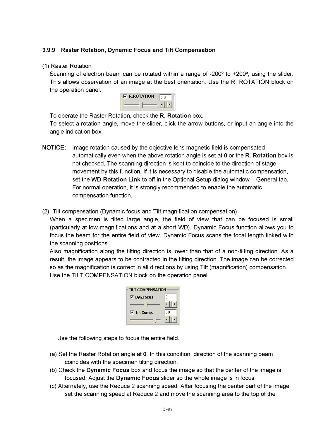
Use the TILT COMPENSATION block on the operation panel.
Use the following steps to focus the entire field.
(a)Set the Raster Rotation angle at 0. In this condition, direction of the scanning beam coincides with the specimen tilting direction.
(b)Check the Dynamic Focus box and focus the image so that the center of the image is focused. Adjust the Dynamic Focus slider so the whole image is in focus.
(c)Alternately, use the Reduce 2 scanning speed. After focusing the center part of the image, set the scanning speed at Reduce 2 and move the scanning area to the top of the
