3.5.7.2 Movable range and specimen exchange position
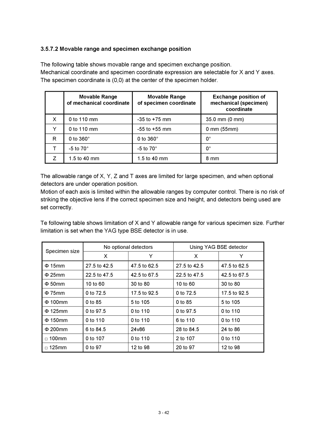
The following table shows movable range and specimen exchange position.
Mechanical coordinate and specimen coordinate expression are selectable for X and Y axes. The specimen coordinate is (0,0) at the center of the specimen holder.
| Movable Range | Movable Range | Exchange position of |
| of mechanical coordinate | of specimen coordinate | mechanical (specimen) |
|
|
| coordinate |
X | 0 to 110 mm | 35.0 mm (0 mm) | |
|
|
|
|
Y | 0 to 110 mm | 0 mm (55mm) | |
|
|
|
|
R | 0 to 360° | 0 to 360° | 0° |
|
|
|
|
T | 0° | ||
|
|
|
|
Z | 1.5 to 40 mm | 1.5 to 40 mm | 8 mm |
|
|
|
|
The allowable range of X, Y, Z and T axes are limited for large specimen, and when optional detectors are under operation position.
Motion of each axis is limited within the allowable ranges by computer control. There is no risk of striking the objective lens if the correct specimen size and height, and detectors being used are set correctly.
Te following table shows limitation of X and Y allowable range for various specimen size. Further limitation is set when the YAG type BSE detector is in use.
Specimen size | No optional detectors | Using YAG BSE detector | |||
|
|
|
| ||
X | Y | X | Y | ||
| |||||
|
|
|
|
| |
Φ 15mm | 27.5 to 42.5 | 47.5 to 62.5 | 27.5 to 42.5 | 47.5 to 62.5 | |
|
|
|
|
| |
Φ 25mm | 22.5 to 47.5 | 42.5 to 67.5 | 22.5 to 47.5 | 42.5 to 67.5 | |
|
|
|
|
| |
Φ 50mm | 10 to 60 | 30 to 80 | 10 to 60 | 30 to 80 | |
|
|
|
|
| |
Φ 75mm | 0 to 72.5 | 17.5 to 92.5 | 0 to 72.5 | 17.5 to 92.5 | |
|
|
|
|
| |
Φ 100mm | 0 to 85 | 5 to 105 | 0 to 85 | 5 to 105 | |
|
|
|
|
| |
Φ 125mm | 0 to 97.5 | 0 to 110 | 0 to 97.5 | 0 to 110 | |
|
|
|
|
| |
Φ 150mm | 0 to 110 | 0 to 110 | 6 to 110 | 0 to 110 | |
|
|
|
|
| |
Φ 200mm | 6 to 84.5 | 24v86 | 28 to 84.5 | 24 to 86 | |
|
|
|
|
| |
□ 100mm | 0 to 107 | 0 to 110 | 2 to 107 | 0 to 110 | |
|
|
|
|
| |
□ 125mm | 0 to 97 | 12 to 98 | 20 to 97 | 12 to 98 | |
|
|
|
|
| |
3 - 42