For
Page
Foreword
Foreword
Details of Guarantee
Period of Guarantee
Exclusions from Guarantee
Limitations on Guarantee
After-sales Service
Installation
Available Training Programs
Safety Summary
Maintenance of Warning Labels
Safety SUMMARYcont’d
Electrical Hazard
High Temperature Hazard
Laser light Hazard
Fig S-1 Warning labels on the Main unit standard version
Fig S-2 Warning labels on the Display unit standard version
Pinch
Fig S-3 Warning labels on the Main unit Ansi style labels
Fig S-3 Warning labels on the Display unit Ansi style labels
Beware
Beware of high Rotary Pump Temperature
Electric shock
Electron Gun / Ion pump Baking
Laser Light
Water Leakage Detection
Backup of Important Data
Third Party’s Industrial or Proprietary Rights
Cooling Water
Third Party’s Application Programs
Do Not Change Computer Settings
Protection against Computer Viruses
Personal Computer PC
Power Failure
Fig S- 5 Location of Emergency Off button
Emergency Off Button
Power Supply and Grounding Connection
Main Power Disconnect
Unit power supply
Baking power supply
Electron Gun
Ion Pump
Fig S- 6 Location of safety interlock
Safety
Safety
Fig S- 9 Gravity location of Main unit Type1
Fig S- 10 Gravity location of Main unit Type2
Fig S- 11 Gravity location of Display unit
Fig S- 12 An example of the water-leakage detector
Precautions on Handling
Precaution
General Precautions
Others
Flashing
Status Transition of Adsorbed Gas Molecules on Cathode Tip
Precaution
Electron Optics
Magnification
Display Unit
Specimen Stage
Protection Devices
Evacuation System
Physical Dimensions
Power Requirements
Installation Environment
∝m Peak to Peak
Oscillation Allowable Amplitude X, Y
Oscillation Allowable Amplitude Z
Water Supply and Drain
Model S-4800 Field Emission Scanning Electron Microscope
Table of Contents Cont’d
Functions
Table of Contents Cont’d
Maintenance
Replacement Parts
Room Temperature and Humidity
Installation Requirements General
Grounding
Line Power Requirement
Stray Magnetic Field
Allowable Vibration
Floor Vibration
Vibration Allowable Amplitude X, Y
Vibration Allowable Amplitude Z
Vibration Transmittance Frequency Characteristics
External Noise Sources
Power Line Noise and Electric Field Noise
Site Requirements
Disturbance by Sound Waves
Installation Layout example
Materials or Instruments to be prepared by User
Wiring
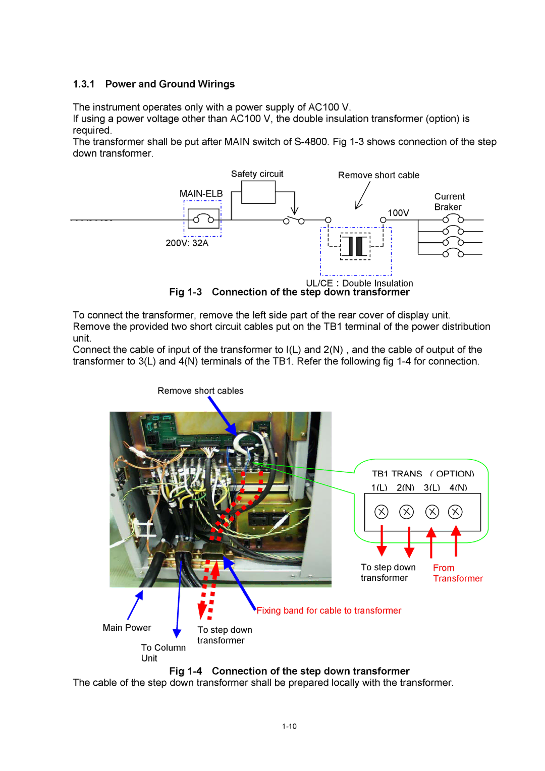
Connection of the step down transformer
Power and Ground Wirings
100/200V Safety circuit
Functions
S-4800 Main Unit type
Control Knobs and Switches on Main Unit Main unit Column
Sectional View of S-4800 Column
Specimen Stage type
Large Specimen Stage type
Specimen exchange device
Evacuating System
8a Evacuation Control Panel
8a Display / Operation area
IP1
Page
Page
Shows the display unit
Control Knobs and Switches on Display Unit
10 PC Panel
PC power switch
12 Mouse
Administrator Administrator level, no password
Initially following users are set when sipped
4800 Power user level, no password
15 S-4800 Loin dialog window
16 S-4800 Main window
2 S-4800 SEM Main Window
Page
Page
Open SEM Data Manager Opens the SEM Data Manager window
Menu
Direct Save
Direct Photo
Column
Mag Mode
Condition Load
Condition Save
Run Freeze
Split DM Mode
Capture
Capture Reso
Optional Setup Stage
Optional Setup
Optional Setup General
Login Setting
ECO mode setting
Maintenance
Functional blocks on the Control Panel
Control Panel
18 Control panel HV control block
Vacc select
Execute button
Intensity
Auto control
Scan control block
Magnification control
Monitoring function Align
Capture button
Image recording
Page
19 Control Panel Dual screen mode Run / Freeze buttons
Extension for Dual screen mode
20 Operation panel
Operation Panel
Signal Select block
OPE Condition block
6.3 R.ROTATION block
Scan Mode block
Data Entry block
Scan Size block
Smooth
Signal Processing block
Sharpen
Edge Enhance
Color Mixing block
Tilt Compensation block
Other optional function block
Scroll bar and area marker block
Arrangement of control blocks
Mouse operation on the scanning image
21 Mouse Focus/stigma/contrast/brightness adjustment
Exchanging mouse control functions
22 Mouse control Focus/stigma/contrast/brightness
Page
Stage and image shift tools
Setup dialog window
23 Mouse control stage
Column tab
Page
Image tab
1Auto Data Display
Record tab
5Embed into Image checkbox
1Memory Photo
1Film Speed
24 Condition Load/Save
8.4 OP. Cond tab
Captured Image Window
Reset All button
Reset button
SEM Data Manager Window
Alignment Dialog Window
Comm Port Selects one of communication ports Speed
Oblique Dialog Window
Password Setting Dialog Window
Save Image Dialog Window
Opt Signal Processing Dialog Window
Split/Dual Mag Controller
Using Short-Cut Keys
Operation
Display Power
Preliminary Operation Check of Column Vacuum
Flow the cooling water
Starting the Display
Use of Anti-Contamination Trap
Specimen Preparation for Materials
Specimen Setting and Specimen Exchange
Specimen Exchange Position
Adjustment of Specimen Height
Extracting specimen from stage
How to Set Specimen
Page
Opening the specimen exchange chamber door
Setting a specimen
Turn the knob clockwise so as the Unlock mark comes upwards
Flashing About flashing
Flashing Procedure
Accelerating VoltageEmission Current
Setting of Accelerating Voltage and Emission Current
Application of High Voltage
High Mag mode
Optimizing the Electron Beam Selecting a Magnification Mode
Selecting Electron Optical Column Condition
Objective lens Specimen
Low Mag mode area
Page
Low Mag Mode
Column Alignment Operation
Circular image Adjust
Page
WD mm Lowest magnification High Mag Mode
SE detector
Operation for Image Observation
BSE-H
Signal Control
General Characteristic of signals utilized in S-4800
Page
Selecting Magnification
Selecting Scanning Speed
Slow 4 38 sec/frameFull screen
Image Brightness and Contrast Adjustment
Page
Page
Focus and Astigmatism Correction
Page
Defocusedfocused
Movable range and specimen exchange position
Operation of the Specimen Stage Type I Manual Stage
Movable range limitation of X, Y and R axes
Tilt and Z axes limitation
6.4 3 axes motorized stage Type1 stage option
Stage Locking
Movable range of X and Y directions 3 axes motorized stage
Coordinate notation
Movable range and specimen exchange position
Specimen block
Setting specimen size and detectors in use
Valious operation for specimen stage
Stage tab
Upper button Ball Lower button
7.6 X, Y, R axes operation
Tilt axes operation
Page
Stage mouse operation on the scanning image
Page
Page
Page
Page
Adjust tool
Position memory function
Stage History function
Image Navigation
Page
Rotation Assist function
35、-55 75,-55 62.5,0 35,0 50,10 -34,10 35,55 75,55
Rotation / tilt eucentric function and calibration
Calibration Following calibration commands are provided
Page
Page
Page
Stage lock
Stopping stage and Returning to previous stage position
Moveable range and limitation by optional detectors
Φ75 specimen
XY movable range for various specimen size
Allowable minus Tilting angle
Allowable plus Tilting angle for various specimen size
Saving and Recording Images
Preparing Images for Recording
Setting Conditions for Image Capturing
Image Capturing
Manager
Saving a Scanning Image Direct Save
Taking Photographs Option
Saving Captured Images
Page
Photographing saved images
Using SEM Data Manager
Turning High Voltage Off
Setting the Stage at the Specimen Exchange Position
Taking Out a Specimen
Page
Closing Windows and Shutting the Display Power
Screen Mode
Using Other Functions
Page
Split Screen and Dual Mag Mode
Signal Selection and Color Mixing
Page
Ray Analysis Mode
Drag the cursor with the mouse
Signal Processing
Page
Operating Condition Memory
Page
Data Entry Function
Pseudo Color Display
Page
Show
Raster Rotation, Dynamic Focus and Tilt Compensation
Page
Printing images using Report generation function
100
Copy Image information text
Oblique Image
Optional setting
104
Setting Login Name
106
Accelerating Voltage and Image Quality
Image Quality
Objective Lens Aperture Size and Image Quality
Condenser Lens Setting and Image Quality
Preparative Operation for Alignment
Mechanical Column Alignment
Alignment of the Beam Monitor Aperture
Mechanical Alignment of the Electron Gun
Mechanical Alignment of the First Condenser Lens
Alignment of the Objective Lens Aperture
Mechanical Alignment of the Second Condenser Lens
Aperture Alignment electro-magnetic alignment
Stigma Alignment electro-magnetic alignment
113
Precaution About SEM Data Manager
Functions 3.12.2.1 Image Database
Menu and tool buttons
117
118
Operation Registering Images on SEM Data Manager Database
Selecting User name and opening data tree
121
Viewer display
Image information
Data Entry
123
124
Contrast Conversion
→ →
127
Image Processing
Color Mixing
130
Image file operation
Printing images
132
133
Slide show
Optimizing and repairing database file
Replacement and Cleaning of Objective Lens Aperture
Maintenance
Objective Lens Aperture unit
Cleaning of Aperture Plates
Baking of Aperture Plate
Oil Change
Replacement of Oil Mist Trap
Symptom Cause Countermeasure
Troubleshooting
Checkup and Maintenance
Page
Symptom Probable Cause Remedy
Troubleshooting of Air Compressor
Location and Functions of Major Components
When Specimen Exchange Chamber Vacuum is not Good
Troubleshooting When Column Evacuation does not Work
When Ion Pump Vacuum Degraded
When Specimen Chamber Vacuum is not Good
When Image is not Shown on Screen
When Emission Current is not Set at Normal Value
When Image is Very Noisy
When Auto Focus or Auto Stigma does not Work Satisfactorily
When You cannot Correct Astigmatism
When PC has Hanged up
When S-4800 control program does not start up
Operation for shutting down all power supply of S-4800
When Error Messages are shown
Operation when power was shut down by power line failure
Operation for Starting S-4800
Operation when Water supply stopped by failure
Operation when power line failure recovered
Gun Baking operation
Beware of high Temperature
Page
Beware of high Temperature
Page
Consumables
Consumables and Spare Parts
Part Name Use Expiration
Replacement Parts
Part Name Location ’ty Used
Spare Parts
Model S-5080 Auto-Camera option
Configuration
Configurations of Various Film Holder Units Option
Remarks
Specifications
Model S-5080 Auto-Camera option
4″ × 5″ Film Magnification
Assembling the Camera
Aperture for Each Kind of Film
Operation
Installation Manual for the SEC Guide Rail for Installer
Index
PRECAUTION-7, PRECAUTION-9, PRECAUTION-11
Edit menu Copy Attribute command 21, 3-101
PRECAUTION-8, PRECAUTION-11
PCI
PRECAUTION-10
Transfer 2-21, 2-31, 2-48, 3-72