The signal intensity of the lower detector significantly decreases at short WD conditions. It is recommended to use the lower detector at a WD of 7mm or longer.
(3) Mixed Signal of Upper and Lower Detectors:
The upper and lower detector signals can be mixed to show characteristics of both detectors. The intensity of this signal does not vary much for a change of WD.
When the U/D Variable is shown with blue color, the ratio of Upper and Lower detector gain follows the contrast settings those previously adjusted in Upper and Lower mode individually. You may control the mixing ratio of upper and lower detector signals.
When it is shown with light gray color, both detectors have the same gain. In this case, the ratio of two signals are changed automatically depending on WD position, and therefore the signal of the upper detector is dominant at shorter working distances, while that of the lower detector is outstanding at longer working distances.
NOTE: If the ABCC Link check box in the Column tab of the Setup dialog window has been checked, ABCC will start automatically when detector selection is changed. Image brightness will be adjusted to adequate value.
3.5.1.1Secondary and backscattered signals and their Characteristics
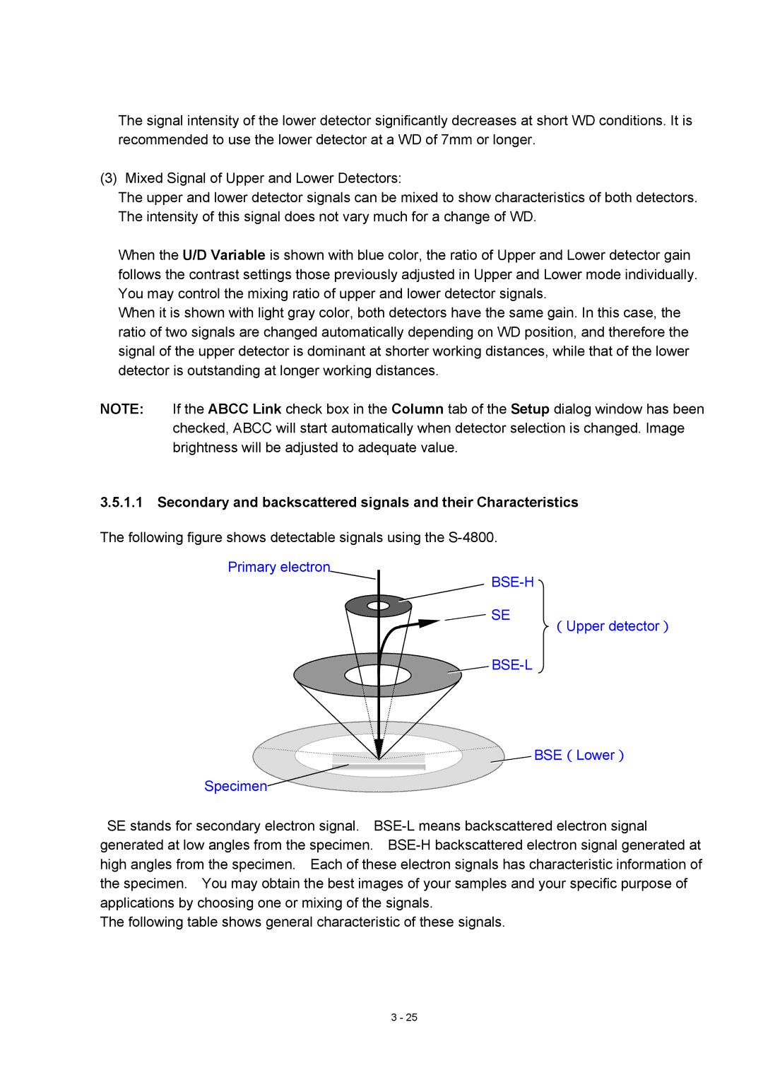
The following figure shows detectable signals using the
Primary electron
BSE-H
SE
(Upper detector)

BSE-L
BSE(Lower)
Specimen
SE stands for secondary electron signal.
The following table shows general characteristic of these signals.
3 - 25
