Area Code Change
Comsphere 6800 Series Network Management System
Copyright � 1997 Paradyne Corporation. All rights reserved
Warranty, Sales, and Service Information
Trademarks
Important Safety Instructions
FC F C F CC
Table of Contents
Connecting the Components
Running Diagnostics
List of Figures
Comsphere 6800 Series Network Management System
Vii
List of Tables
Abstract
Objectives And Reader Assumptions
Typeface
Documentation Conventions
Related Documents
Communications Products Support Command Reference Manual
Overview
Introduction
With UIP Ð
5000
5000 Host
Altos
Selecting a Site
Contents List
License Agreements
User Interface Processor
Optional Components
NMS Application Software
Printers
Full-Feature Workstations
Basic-Feature Workstations
User Documentation in addition to this manual
Preparing the Processors
Overview
Hardware
Altos System 5000 Host
Address Description
Circuit Cards
System 5000 Ð Cover Fasteners
Opening the System 5000 Host
System 5000 Ð Disengaging Cover Locking Pins
Integral Ethernet Card
Preinstallation Checks for the Integral Ethernet Card
Optional Host Upgrade Packages
Second and Third Hard Disk Jumper Settings
IPC-900 Ð Switch and Jumper Locations
Preinstallation Steps for the Analysis NMS Package
Preparing the Processors
Emulex DCP-286i Ð Switch and Jumper Locations
DCP/MUXi Ð I/O Address Switch Settings SWI Description
Preinstallation Steps for the 16 Control Channel Package
Installing the Third Hard Drive in the System
Optional Host Upgrade Procedures
Preinstallation Checks for the Token Ring Card
Altos 5000 Disk Bay
Installing Circuit Cards in the System
System 5000 Ð Expansion Slots
10. Emulex DCP/MUCi Ð Circuit Card and Cable Assembly
Installing the Octopus Cable Assembly
Closing the System
Connecting the Ethernet Card to the Network
Converting Host Processor R3.x to R4.2
11 -Port Cabinet Assembly
Installing the 16-Port Cabinet Assembly
12 -Pin Headers P3 and P4 Connector Identification
Altos System 5000 UIP
13. IPC-1600 Ports Cabinet Assembly
Opening the Altos 5000 UIP
Installing Additional Memory on the System
Type
Press Enter
Preinstallation Checks for the Integral Ethernet Card
Boot
Serial Port Upgrade Package for the UIP
Optional UIP Upgrade Packages
14. IPC-1600 Ð Switch and Jumper Locations and Settings
Preinstallation Steps for the IPC-1600 Upgrade Card
Converting Altos 5000 Processors to Release 4.2 UIPs
Optional UIP Upgrade Procedures
Closing the Altos 5000 UIP
UIP Conversion Procedures
Installing the 16-Port Cabinet Assembly
Altos System
Opening the System
15. System 15000 Ð Removing the Top Cover
16. System 15000 Ð Removing the Side Panel
17. System 15000 Ð Removing the Front Panel
18. Altos 15000 Main Processor Card and MPX
Installing the MPX Processor
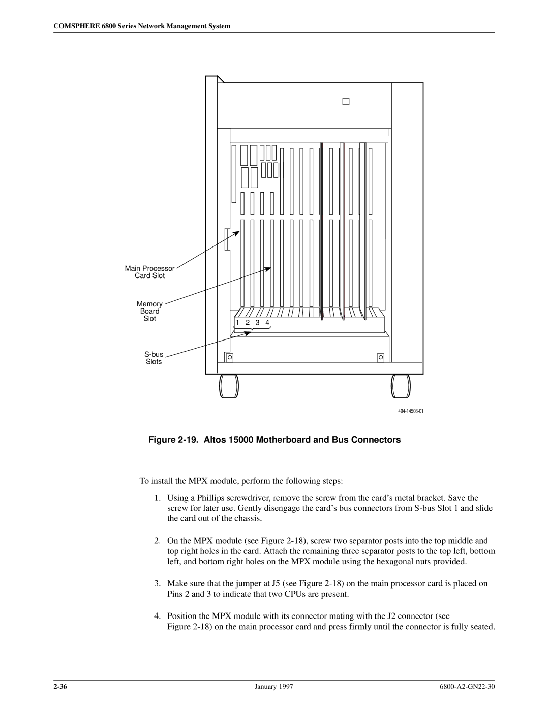
19. Altos 15000 Motherboard and Bus Connectors
Installing the Second and Third Hard Disks on the System
20. Altos 15000 Showing the Hard Disk Bay
Installing the Second and Third Hard Disks in the System
21. Altos 15000 Memory Board and Memory Modules
IPC-1600 Ð Memory Switch Settings DSI Switches
Preinstallation Steps for the IPC-1600 Card on the System
DCP-MUXI Ð I/O Address Switch Settings Description
Preinstallation Steps for the DCP-MUXi Cards on the System
22. System 15000 Ð Expansion Slots
Closing the System
23. System 15000 Ð Top Cover Locking Pins
Press Esc
Running Cmos Setup on the Altos
Eisa Configuration Utility
To select boot from floppy
Press spacebar to interrupt autoboot
25. Main Menu
Loading configuration files Please wait
Type
Changing the Token Ring Configuration
Type d
Preinstallation Checks for the EtherLink II Card
Full-Feature Workstation
Token Ring I/O Address Switch Setting Switches
Installation of the Token Ring Network Interface Card
28. Proteon p1392 Card
Switching off the Cache on 486DX
6386/25 Circuit Cards to Be Removed Release
29. NAU Memory Jumper Locations and Settings
Want to QUIT?
Full-Feature Workstation
Comsphere 6800 Series Network Management System
Preparing the Printers
DL5600 Ð Front Control Panel
Fujitsu DL5600
SET
10 CPI
LPI
11.0
9600
BIT
8NONE
DL3400 Ð Front Control Panel
Fujitsu DL3400
DL3400 Ð Setup Mode Opening Menu
13.6INCH
Cour
10CPI
Comsphere 6800 Series Network Management System
DL3600 Ð Front Control Panel
Fujitsu DL3600
Emulate DPL24C+ Font Cour Quality Letter Pitch
DL3600 Ð Hardware Settings Correct Value
Fujitsu DX2300
DX2300 Ð Memory and Serial Interface Card Access
DX2300 Ð Memory Card Settings
Memory Card DIP Switch Settings Function
DX2300 Ð Serial Interface Card Settings 9600 Baud
Serial Interface Card Settings Switches 6Ð8 Speed
Serial Interface Card Settings Switches 1Ð5 Function
Itoh C-240
Printer Functions Printout Function No Menu No Status
Remote Printing with the Unix SCO/S5R4 Print Spooler
Configuring Network Printers
Network Printers
Aaaa /usr/spool/lp/bin/rlpcmd bbbb /usr/bin/lp ± d cccc
Press Enter Press Esc
Do you wish to continue?
Remote Printing with the BSD Unix Print Spooler
IP-address remotehostname
IPaddress localhostname
System then prompts
Would you like this to be the system default printer? y/n
Connecting the Components
Overview
Altos System 5000 Ð Display Unit, Keyboard, and Mouse Ports
System Console
Altos System 15000 Ð Display Unit, Keyboard, and Mouse Ports
Altos 5000 Full-Feature Workstation Configuration
Connecting the Components
Local Area Network with Second Full-Feature Workstation
Connecting the Second Full-Feature Workstation
Network Hub Unit
Local Area Network with UIP
Connecting the Third Full-Feature Workstation
Local Area Network with Additional Full-Feature Workstations
Connecting the Basic Configuration
Altos 15000 Full-Feature Workstation Configuration
Connecting Additional Full-Feature Workstations
Cascading Network Hub Units
Altos 15000 Cascaded Network Hub Units
Cascaded Hub Cable Modifications End Connects To
Basic-Feature Workstation
10. Basic-Feature Workstation Configurations
11. Basic-Feature Workstation Configurations
Connecting a Remote AT&T 6286 or
Connecting a Local AT&T 6286 or
NMS Printer Models Function
Printers
DL3400/DL3600
Connecting a Local System Printer
DX2300
Connecting a Remote System Printer
Connecting an Alert Log Printer
DL5600
240
Connecting the Dedicated Automatic Trouble Report Printer
Data Communications Equipment
Connecting Modems and DSUs
13. Daisy Chain
Using a Hubbing Device
14. Local Control Channel Connections
Connecting Locally
Materials Required
15. Remote Control Channel Connections
Connecting Remotely
Connection Procedures
Configuration Options
Connecting Acculink Multiplexers
16. Connections for 719 Networker to Host Processor
17. Connections for Two Local Acculink Multiplexers
One Local Acculink Multiplexer and One 719 Networker
19. Connections for One Local Acculink Multiplexer
Connection Procedures
Connecting the Current Version 719 Networker
Connecting the Earlier Version 719 Networker
External Systems
Connecting the 719 Networker to the 74x Multiplexer
20. External Systems Connections
Connecting a Remote System Controller
Connecting a Local System Controller
Connecting a Remote Dial Backup Control Unit
Connecting a Local Dial Backup Control Unit
Connecting a Remote Service Restoration Control Unit
Connecting a Local Service Restoration Control Unit
Connecting a Remote DCX Multiplexer
Connecting a Local DCX Multiplexer
Connecting a Computer System Requiring VT100 Emulation
Connecting Remotely
Netview/PC
Connecting Locally
Connecting Remotely
22. ATR Connection
Automatic Trouble Report Feature
Accumaster Integrator
Connecting the Components
24. Accumaster Integrator Remote Connection
Connecting the Components
Analysis Network Management System
Connecting the Analysis
Connecting the Analysis 6510/5605
26. Analysis 6510/5605 and 5600 Remote Connection
Connecting the Analysis 6510/5605
27. StarKeeper Connection
StarKeeper Network Management System
Connecting Remotely
Bytex UMS
Connecting the Host Processor to the Bytex UMS
Connecting the UIP to the Bytex UMS
Loading and Restoring Software
UIP Application Software
Full-Feature Workstation Software
Basic-Feature Workstation Software
MPX Multiprocessing Software
Order of Installation
Basic Network Configuration
Network Preinstallation Preparation
Customized Network Configuration
Unix Software for the Host Processor
Inserting the Software Media
System 5000 Boot Menu Installing Unix on Host Computer
Press space bar to interrupt autoboot
Installation Procedure Menu Installing Unix on Host Computer
Hardware Configuration Menu Installing Unix on Host Computer
Enter your activation key or enter q to quit
New password
Re-enter new password
Init Single User Mode
Enter the system node name or enter return to use unix
Done reading tape
Add chain altostcp aaa y/n
Adding altostcp aaa Enable aaa driver
Select top level of chain to Add or q to quit
Select next level of chain to Add or q to quit
Press Enter to continue
Disabled
Installing Altos TCP/IP over aaa
OAddrRange Interface 6c80\N6caf
Internet Address Netmask Broadcast Address
Enter the netmask for this interface default
Enter the internet address of this interface
Do you want to relink the kernel now?
Strike Enter when ready
System displays the following prompt
Do you want the kernel environment rebuilt? y/n Type y
Do you want this kernel to boot by default? y/n Type y
Press Cntl-d
Installing the MPX Software on the Altos
Press any key to continue
Enter your Altos MPX serial number
Enter your Altos MPX activation key
Do you wish to create a new kernel now y/n? Type y
Release 4.2 NMS Software
Installing the NMS Software
Etc/tz
Installing NMS Release
Type help85 Press Enter
How many UIPs do you have 0, 1, or 2 Type n
Type cd Press Enter
Do you wish to have the screen-saver capability y/n n
Formatting the Third Hard Disk
Safe to Power Off Press Any Key to Reboot
3rd hard disk is already installed
Software installation of the 3rd hard disk is complete
Do you want to install a 3rd hard disk? y/n/q
Installing the 3rd hard disk. Please wait
Type root
Initializing the NMS Database
Option Explanation
NMS Parameters Menu Ð Options
Nnn.nnn.nnn.nnn uip-name
Network Configuration of NMS Host
Nnn.nnn.nnn.nnn ffw-name
Remove altostcp aaa y/n
Altostcp aaa Select a chain to remove
Press Press Enter
System displays status messages and then request
Do you want this kernel to boot by default? y/n?
TCP/IP Configuration Complete
Installing Token Ring Software on the NMS Host/UIP
Products Currently Installed menu appears Type q
Configuring the Token Ring Network on the 5000 Host/UIP
Add chain altostcp-pro0 y/n Type y
Select top level of chain to Add or q to quit Type
System prompts for the card slot number
If nn is 99, sufficient pseudo ttys are already configured
Do you want to relink the kernel now? Type y
Unix Software for the UIP
System 5000 Boot Menu Installing Unix on UIP
Installation Procedure Menu Installing Unix on UIP
Hardware Configuration Menu Installing Unix on UIP
Press any key
Strike enter when ready or Esc to stop Press Enter
Add chain altostcp en0 y/n
Interface Address Netmask Broadcast Address
Press Return
Is there an IPC1600 card installed in the system? y/n
Press Ctrl-d
UIP Software
Type y or n as appropriate to your location
Type
Building NMS fonts
What is the name of the NMS Host machine?
Nnn.nnn.nnn.nnn host-name
Network Configuration of NMS UIP
Do you want the kernel environment rebuilt? y/n appears
Type
Remove altostcp en0 y/n
Altostcp en0 Select a chain to remove
Type q Press Enter
Do you want to relink the kernel now
Installing Token Ring Software on the UIP
Configuring the Token Ring Network on the UIP
Do you want this kernel to boot by default? y/n
DEVICE=C\/DOS\/EMM386.EXE 2048 M4
Full-Feature Workstation Software
Token Ring Configuration
Installing MS-DOS
EtherLink II Configuration
StarLAN 10 NAU Configuration
Enter the destination directory to use \/XONE Press Enter
Enter the floppy drive to use a Press Enter
Enter the destination drive to use C Press Enter
Do you wish to install the DecWindows fonts y/n? n
Do you wish to install the fonts y/n? n Type y
Do you wish to install the 100DPI fonts y/n? n Type y
Do you wish to install the OpenWindows fonts y/n? n
One Setup Utility Press any key to continue Press Enter
Ready to execute setup Press any key to continue Press Enter
Select Monitor Size Inch Other Enter selection of `q to Quit
Insert the proper disk and Press Enter System responds
Enter a subnet mask255.0.0.0
Enter I/O Address in hex
Type Press Enter
Enter this systems IP address
One Setup is now finished
Press Enter
Type edit XONE.CFG
Type y Press Enter
Do you wish to install the DecWindows fonts y/n? n
Type
Type appropriate number
Enter a subnet mask
System asks
Files extracted Press any Key to continue
One install complete Press any Key to continue
Type edit autoexec.bat
Proteon LAN Support Setup
\PROTEON
Selection menu for board type appears
LSP Software Setup Completed Press Enter to continue
Network Configuration of Full-Feature Workstation
Configuring Full-Feature Workstation with a Router Network
Name=remoteportname gateway=1 name=localportname gateway=2
Nnn.nnn.nnn.nnn portname
Press Enter Otherwise, Press Enter
Generic X-Terminal
Basic-Feature Workstation Software
Installing MS-DOS
Installing NMW Software
Installing Microsoft Windows
Return to the root directory. To do this, Type cd \
Type root Press Enter
Installing the Analysis Gateway Option 5000 Systems Only
Installation
Password
System prompts for the value of the starting I/O address
Type D2000 Press Enter
Type 2B0
Do you want the kernel to boot by default? y/n Type y
Configuration
Analysis Selection Menu
Enter Analysis 6510 name, 15 characters max
How many local terminals 1 Ð 6 are configured on this 6510?
Adding a 6510 to the 6800 Series NMS
To exit the configuration process, Type
System Name CC Name Port #
Changing 6510 Parameters
Do you wish to see a system summary? y or n
Parameters successfully changed
Enter Analysis 6510 name, 15 characters max ªsystem nameº
Select port number from list 1,2,3,4,5,6,7,8
Removing a 6510 Configuration
ªSystem nameº removed from the system
Setting Data Rates
Elapsed Time
UIP Start-Up and Shutdown
System Start-Up and Shutdown
Type nms Press Enter
Starting Unix on the Host
Starting the NMS Application Program
Type ffw Press Enter
Type admin Press Enter
FFW Login Window
Manager Window
Shutting Down the NMS Application Program
They will be shut down? y/n n
Log off now or risk your files being damaged
Shutting Down Unix on the Host
Are you sure you want to shut down UNIX? y/n
Starting the UIP Application Program
Starting Unix on the UIP
Press Return to continue Press Enter
To select Return to Console Login
Shutting Down the UIP Application Program
Unix will now be shutdown? y/n
Shutting Down Unix on the UIP
Performing Migration
Introduction To Migrating Databases
Databases Migrated
Release 1 Database Migration
Device Name
Cleaning Up the Database
Device Address
Site Name
Device Model
Serial Number
Circuit Name
Site Contact Phone
Select All of the Above Databases. To do this, Type
Backing Up the Database
Migrating the Database
Do you wish to initialize the NMS database y/n n
Do you wish to initialize the Online partition? y/n n
Original Menu Showing Selected Type r1
Enter the previous NMS type sc, r1, r2, r3, r3.1, r4, r4.1
Xxxx Data Base Initialization Completed
Xxxx Data Base Initialization
Starting the AT&T Paradyne NMS system. Please wait
Now rebuild the NMS database indices
To select Start the System
Data Integrity Verification
Checking the Migrated Database
Cd /usr/tmp pg migrate.err pg migrate.out
Profile Data Changes and Corrections
Performing Migration
Release 2 Database Migration
Cleaning Up the Database
Database Backup for Migration Completed
Continue with backup? y/n y
Migrating the Database
Enter the appropriate type, Type r2
Original Menu Showing Selected Type r2
Do you wish to migrate faults data y or n? n
Type c Press Enter
Do you wish to migrate trouble ticket data y or n? n
Do you wish to migrate results queue y or n? n
Press nms Press Enter
Checking the Migrated Database
Release 3.0/3.1 Database Migration
Cd /usr/tmp Pg migdbload.log pg migrestore.log
To migrate the NMS database, perform the following steps
Do you wish to initialize the Online partition? y/n n
Type
Original Menu Showing Selected Type r3
Press Return to continue Press Return
Do you have another level of tapes to restore? y/n
Type nms Press Enter
Checking the Migrated Database
Release 4.0/4.1 Database Migration
Cd /usr/tmp pg initdb.log pg restorelog
Cleaning Up the Database
Do you wish to initialize the Online partition? y/n n
Do you wish to initialize the NMS database? y/n n
Original Menu Showing Selected Type R4
Type n Press Enter
Release 4.2 6800 NMS Main Menu appears. To continue
Checking the Migrated Database
Cd /usr/tmp pg initdb.log pg restorelog
Running Diagnostics
Boot Menu
SDX Diagnostic Program
Do you wish to review summary again y/n Type y
SDX Main Menu
StarLAN IRQ Strapping
StarLAN 10 NAU Diagnostic Program
Format complete, format another?
IPC-900 Diagnostic Program for Altos 5000 Systems Only
Insert new diskette for Drive a and strike enter when ready
After each line. When complete, Press F6
Press Enter
Port-to-Port Connections
Dip Switch Settings for Memory Address
IPC-1600 Diagnostic Program
Type n Press Enter
After each line. When complete, Press F6
Type DCPDIAG2
Emulex DCP/MUXi Diagnostic Program
Type any key to proceed. Press Enter
Select Start Address and Press Enter
CEO Modem
Configuring 3810, 3811, and 3820 Modems
3810, 3811, and 3820 Modems
LCD prompts Save Straps? Yes Ð No
Hardware Option Settings for the 2224-CEO
Software Configuration Option Parameters for the 2224-CEO
O51
Locking Option Changes
O12
O34
Adapter and Cable Identification B
Feature#
Feature #
Analysis Remote
Bytex Switch Connects
System Printer For remote
Workstations For remote
Integrator/Starkeeper
DCX Multiplexers For local
Analysis For local
External Systems Remote
VT100 Emulation Connects
Workstations Connects
IBM NetView/PC Connects
6821-F1-513
M6BC/M4BB
StarKeeper Local
System Controller Local
74x Multiplexers Connects
NetView/PC Connects
Dataphone II Connects
Analysis Connects
DCX Multiplexers Connects
Maintaining Multiplexers C
General Troubleshooting Procedures
Pollpf Multiplexer polling port is down
Command Port Failure
Multiplexer Problems
Monitor
Power Distribution Connection
Figure C-3. Power Connections for 745 Multiplexers
Figure C-4 Power Supply for 740 Multiplexers
Figure C-5 Power Supply Connection for 745 Multiplexers
NAP Speed
Evtpf Multiplexer event port is down
Faulty Connections
Software Configuration Errors
Event Port Failure
NMS Commands
External Systems Port Failure
Event Log Printer Problems