Note- Mak e a note of the positions of the cables connected to the external interface before
disconnectingt hem to ensure that they are reinstalled correctly.
Note- Mak e a note of the positions of the PCIe card cassettes before removing them t o ensure
thatthey are rein stalled correctly.
Note- If no cr ossbar unit is mounted, proceed to step 6.
14.4.1 Accessing the PSU backplane unit1. Lowerthe cable support.
For details, see "5.5.1 Loweringthe cable support."
2. Removeall thecables connected to the external interface.
Theca blest o be removed are as follows.
■Interface cable connected to the PCI Express (PCIe) card
■Crossbarcable
■XSCFBB control cable
■XSCFDUAL control cable
■LANcable
3. Removeall PCIecard cassettes.
For details, see "13.5.2 Removing a PCI Express card cassette."
4. Removeall thecrossbar units.
For details, see "9.4.2 Removing a crossbar unit."
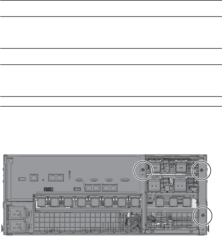
5. Loosenthe three screws securing the mounting frame of the crossbar unit
andthen remove the frame.
Figure14-2 Screwssec uring the mounting frame
Chapter14 Maintaining the PSU Backplane Unit 271