8XC196NP, 80C196NU Microcontroller User’ Manual
8XC196NP, 80C196NU Microcontroller User’s Manual
Intel Corporation
Contents
Chapter Programming Considerations
Contents
Chapter Ports
Programming the Serial Port
EPA Functional Overview
8XC196NP, 80C196NU USER’S Manual
Chapter Interfacing with External Memory
Appendix C Registers Glossary Index
Figures
10-7 Valid EPA Input Events
13-16
Tables
10-5 Example Control Register Settings and EPA Operations
8XC196NP and 80C196NU Signals Arranged by Function
Guide to This Manual
Page
Manual Contents
Chapter Guide to this Manual
8XC196NP, 80C196NU USER’S Manual
Notational Conventions and Terminology
Addresses
Italics
Units of measure
Related Documents
Application Notes, Application Briefs, and Article Reprints
Handbooks and Product Information
Title Order Number
MCS 96 Microcontroller Datasheets Commercial/Express
MCS 96 Microcontroller Datasheets Automotive
8XC196NP, 80C196NU USER’S Manual
Intentionally Left Blank
Intentionally Left Blank
Technical Support
World Wide Web
Product Literature
Page
Architectural Overview
Page
Chapter Architectural Overview
Typical Applications
Features of the 8XC196NP and 80C196NU
Device Features
Block Diagram
ROM
CPU Control
Register File
Register Arithmetic-logic Unit Ralu
Code Execution
Memory Controller
Instruction Format
Interrupt Service
Multiply-accumulate 80C196NU Only
Internal Timing
Clock Circuitry 8XC196NP
Clock Circuitry 80C196NU
25 MHz
State Times at Various Frequencies
12.5 MHz
50 MHz
PLLEN21
Multiplier State Time
1 I/O Ports
Event Processor Array EPA and Timer/Counters
Internal Peripherals
Serial I/O SIO Port
Pulse-width Modulator PWM
Reducing Power Consumption
Special Operating Modes
Testing the Printed Circuit Board
Design Considerations for 80C196NP to 80C196NU Conversions
8XC196NP, 80C196NU USER’S Manual
Advanced Math Features
Page
Chapter Advanced Math Features
Enhanced Multiplication Instructions
Multiply/Accumulate Example Code
Saturation Mode
Operating Modes
Instructions Execution Time
Fractional Mode
Accumulator Register ACC0x
Accstat
Accumulator Control and Status Register Accstat
Bit Function Number Mnemonic
SME FME
Effect of SME and FME Bit Combinations
Description
Programming Considerations
Page
Operand Type No. Signed Possible Values Addressing
Overview of the Instruction SET
Operand Type Definitions
Restrictions
Byte Operands
BIT Operands
SHORT-INTEGER Operands
Integer Operands
Word Operands
DOUBLE-WORD Operands
Converting Operands
LONG-INTEGER Operands
QUAD-WORD Operands
Conditional Jumps
Floating Point Operations
Extended Instructions
EST
Addressing Modes
Indirect Addressing
Direct Addressing
Immediate Addressing
Definition of Temporary Registers
Indirect Addressing with Autoincrement
Extended Indirect Addressing
Extended Indirect Addressing with Autoincrement
Short-indexed Addressing
Indexed Addressing
Indirect Addressing with the Stack Pointer
Long-indexed Addressing
Zero-indexed Addressing
Extended Indexed Addressing
Extended Zero-indexed Addressing
Design Considerations for 1-MBYTE Devices
Assembly Language Addressing Mode Selections
Extended Addressing
Software Standards and Conventions
Addressing 32-bit Operands
Using Registers
Addressing 64-bit Operands
Linking Subroutines
Software Protection Features and Guidelines
Memory Partitions
Page
Chapter Memory Partitions
Memory MAP Overview
FFH 2FH 1FH 0FH F1H
F0H
FFH
Memory Partitions
80C196NP/NU External 83C196NP ROM
XC196NP and 80C196NU Memory Map
Hex Description Addressing Modes
Program and Special-purpose Memory
Program Memory Access for the 83C196NP
External Memory
Program Memory in Page FFH
Special-purpose Memory
Special-purpose Memory Access for the 83C196NP
XC196NP and 80C196NU Special-purpose Memory Addresses
Reserved Memory Locations
Chip Configuration Bytes
Peripheral Special-function Registers SFRs
Interrupt and PTS Vectors
Peripheral SFRs
1F7AH
1F7EH
1F7CH
1F4EH
Stack Pointer
CPU SFRs
Stack Pointer SP
Register File Memory Addresses
General-purpose Register RAM
Address Description Addressing Modes Range
8XC196NP CPU SFRs Address High Odd Byte Low Even Byte
CPU Special-function Registers SFRs
CPU SFRs
80C196NU CPU SFRs Address High Odd Byte Low Even Byte
Windowing
8XC196NP
Hlden
Selecting a Window
WSR
Bit Function
Selecting a Window of the Upper Register File
Addressing a Location Through a Window
Peripheral SFRs
10. Windows
Base WSR or WSR1 Value WSR Value for
Upper Register File
2.2 64-byte Windowing Example
11. Windowed Base Addresses
2.1 32-byte Windowing Example
2.3 128-byte Windowing Example
Using the Linker Locator to Set Up a Window
Unsupported Locations Windowing Example 8XC196NP Only
Type Base Length Alignment
This listing shows the disassembled code
Windowing and Addressing Modes
Remapping Internal ROM 83C196NP only
Fetching Instructions
Accessing Data
Fetching Code and Data in the 1-MBYTE and 64-KBYTE Modes
Epcpc
Formation of Extended and Nonextended Addresses
Code Fetches in the 1-Mbyte Mode
Code Fetches in the 64-Kbyte Mode
Data Fetches in the 1-Mbyte and 64-Kbyte Modes
80C196NP and 80C196NU
RD# WR#
Memory Configuration Examples
Example 1 Using the 64-Kbyte Mode
CE#
80C196NP and 80C196NU External flash memory
12. Memory Map for the System in Figure
Address Description
80C196NP and 80C196NU Unimplemented
Ffffffh D70 OE# WE#
Example 2 a 64-Kbyte System with Additional Data Storage
RD# WR# CE#
02FFFFH
13. Memory Map for the System in Figure
80C196NP and 80C196NU External RAM
01FFFFH
Example 3 Using 1-Mbyte Mode
OE# WE# OE# WRH# WRL# RD#
80C196NP and 80C196NU External memory
14. Memory Map for the System in Figure
Fbffffh
Standard and PTS Interrupts
Page
Chapter Standard and PTS Interrupts
Overview of Interrupts
Flow Diagram for PTS and Standard Interrupts
Interrupt Signals
Interrupt Signals and Registers
Interrupt and PTS Control and Status Registers
Intpend
Interrupt Sources and Priorities
Special Interrupts
Ptssel
Unimplemented Opcode
Interrupt Controller PTS Service
Interrupt Sources, Vectors, and Priorities
Software Trap
End-of-PTS Interrupts
External Interrupt Pins
Multiplexed Interrupt Sources
1.3 NMI
Interrupt Latency
Situations that Increase Interrupt Latency
Calculating Latency
Standard Interrupt Latency
Standard Interrupt Response Time PTS Interrupt Latency
Programming the Interrupts
PTS Mode Execution Time in State Times
Execution Times for PTS Cycles
Ptssel
Programming Considerations for Multiplexed Interrupts
Bit Mnemonic Interrupt PTS Vector
EPA0 EXTINT1 EXTINT0 OVRTM2 OVRTM1
Intmask
Bit Mnemonic Interrupt Standard Vector
NMI EXTINT3 EXTINT2
Modifying Interrupt Priorities
INTMASK1
EPA3 EPA2 EPA1
RET Cseg AT 0FF200CH
Determining the Source of an Interrupt
Interrupt Pending Intpend Register
Intpend
Initializing the PTS Control Blocks
INTPEND1
Specifying the PTS Count
PWM Toggle Mode
PWM Remap Mode
Single Transfer
Ptssrv
Selecting the PTS Mode
EPA3 EPA2 EPA1 EXTINT0 OVRTM1 OVRTM2
Ptscon
Single Transfer Mode
Address Ptspcb +
Register Location Function
PTS Single Transfer Mode Control Block
Ptsdst HI Ptsdst LO Ptssrc HI Ptssrc LO Ptscon Ptscount
Ptsdst Ptscb +
8XC196NP, 80C196NU USER’S Manual
Block Transfer Mode Ptscb
Block Transfer Mode
Single Transfer Mode Ptscb
Ptscount = 09H
PTS Block Transfer Mode Control Block
Ptsblock Ptscb +
Increment the contents of Ptssrc after each byte or word
Comparison of PWM Modes
PWM Toggle Mode PWM Remap Mode
PWM Modes
PTSCONST2
PWM Toggle Mode Example
14. a Generic PWM Waveform
PWM Toggle Mode Ptscb
PTSCONST1 HI = T1 HI PTSCONST1 LO = T1 LO PTSPTR1 HI = 1FH
PTSCONST1 H
PTSCONST2 H
PTSCONST2 L
PTSCONST1 L
Ptscon Ptscb +
Tmod
16. EPA and PTS Operations for the PWM Toggle Mode Example
PWM Remap Mode Example
PWM Remap Mode Ptscb
PTS PWM Remap Mode Control Block
PTSCONST1 HI PTSCONST1 LO PTSPTR1 HI PTSPTR1 LO Ptscon
PTS PWM Remap Mode Control Block Register
PWM Tmod
18. EPA and PTS Operations for the PWM Remap Mode Example
Ports
Page
Device I/O Ports
I/O Ports Overview
Bidirectional Ports
Port Bits Type
Bidirectional Port Pins
Port Pin Special-function Associated Signals
Bidirectional Port Operation
Bidirectional Port Control and Status Registers
8XC196NP, 80C196NU USER’S Manual
Bidirectional Port Structure
Logic Table for Bidirectional Ports in I/O Mode
Sfdir
Bidirectional Port Pin Configurations
Control Register Values for Each Configuration
Bidirectional Port Pin Configuration Example
Port Configuration Example
Bidirectional Port Considerations
HZ1
P2.7/CLKOUT
Design Considerations for External Interrupt Inputs
Eport Pins
Port Pin Extended-address Signal Type
Eport
Eport Operation
10. Eport Control and Status Registers
Eport Block Diagram
Complementary Output Mode
Reset
Output Enable
Open-drain Output Mode
Eport Structure
12. Logic Table for Eport in Address Mode
Input Mode
11. Logic Table for Eport in I/O Mode
Epmode Epdir Epreg
Configuring Eport Pins for I/O
Configuring Eport Pins
Configuring Eport Pins for Extended-address Functions
13. Configuration Register Settings for Eport Pins
Eport Considerations
Eport Status During Instruction Execution
Design Considerations
Page
Serial I/O SIO Port
Page
SIO Block Diagram
Serial I/O SIO Port Functional Overview
Serial Port Control and Status Registers
Serial I/O Port Signals and Registers
Serial Port Signals
Serial
Sbuftx 1FBAH
P1REG 1FD4H
Sbufrx 1FB8H
Spbaud 1FBCH,1FBDH
Serial Port Modes
Synchronous Mode Mode
Spstatus 1FB9H
Mode 0 Timing
Asynchronous Modes Modes 1, 2,
Serial Port Frames for Mode
Mode
Serial Port Frames in Mode 2
Mode 2 and 3 Timings
Programming the Control Register
Configuring the Serial Port Pins
Programming the Serial Port
Programming the Baud Rate and Clock Source
PAR TB8 PRS REN PEN
Spcon
PAR
Spcon
Spbaud
Baud Rate Spbaud Register Value Note Error Mode Mode 1, 2
Spbaud Values When Using the Internal Clock at 25 MHz
8A2BH
Determining Serial Port Status
Baud Rate Spbaud Register Value † Error Mode
Enabling the Serial Port Interrupts
8A2CH
RPE/RB8 TXE
Spstatus
RPE/RB8
Serial I/O SIO Port
Page
Pulse-width Modulator
Page
PWM Block Diagram 8XC196NP Only
PWM Functional Overview
PWM Signals and Registers
PWM Signals
PWM Operation
PWM Control and Status Registers
8XC196NP, 80C196NU USER’S Manual
E6H
Enabled
Programming the Frequency and Period
FFH
CLK0
PWM Output Frequencies 8XC196NP
PWM Output Frequencies 80C196NU
CLK1 CLK0
FEH
Programming the Duty Cycle
CONREG0
CLK1 CLK0
PWM xCONTROL Address
Disabled
Clock Prescaler
PWM Duty Cycle
Enabling the PWM Outputs
PWM Output Alternate Port Function PWM Output Enabled When
Sample Calculations
PWM Output Alternate Functions
D/A Buffer Block Diagram
Event Processor Array EPA
Page
Chapter Event Processor Array EPA
EPA Functional Overview
Port Pin EPA Signals
EPA and TIMER/COUNTER Signals and Registers
EPA and Timer/Counter Signals
EPA
EPA Control and Status Registers
TIMER1
TIMER2
TIMER/COUNTER Functional Overview
EPA Timer/Counters
Cascade Mode Timer 2 Only
Quadrature Clocking Mode
Quadrature Mode Interface Quadrature Mode Truth Table
Quadrature Mode Timing and Count
EPA Channel Functional Overview
Operating in Capture Mode
A Single EPA Capture/Compare Channel
EPA Simplified Input-capture Structure
EPA Overruns
Action Taken when a Valid Edge Occurs
Action taken when a valid edge occurs
EPAxCON.0
Preventing EPA Overruns
Operating in Compare Mode
Generating a Low-speed PWM Output
Generating a Medium-speed PWM Output
Generating a High-speed PWM Output
Programming the Timers
Programming the EPA and TIMER/COUNTERS
Configuring the EPA and Timer/Counter Port Pins
Generating the Highest-speed PWM Output
T1CONTROL
Prescaler Divisor Resolution †
Clock Source Direction Source
Prescaler Resolution †
T2CONTROL
Mode ROT ON/RT
Example Control Register Settings and EPA Operations
Programming the Capture/Compare Channels
= 1 = 0
EPA xCON Address Reset State 00H
ROT ON/RT
Capture Mode Event
Compare Mode Action
Compare Mode RT
Capture Mode on
ROT
Determining Event Status
Enabling the EPA Interrupts
Epamask
12. EPA Interrupt Pending Epapend Register
Epapend †
Programming Examples for EPA Channels
EPA Capture Event Program
EPA PWM Output Program
Unsigned char Unused Ptscon
10-27
Page
Minimum Hardware Considerations
Page
Signal
Minimum Required Signals
Minimum Connections
Unused Inputs
I/O Port Configuration Guide
Port Where to Find Configuration Information
11.1.2 I/O Port Pin Connections
Minimum Hardware Connections
Applying and Removing Power
Noise Protection Tips
ON-CHIP Oscillator Circuitry
On-chip Oscillator Circuit
External Crystal Connections
Using AN External Clock Source
External Clock Connections
Resetting the Device
Reset Timing Sequence
Generating an External Reset
Internal Reset Circuitry
Minimum Reset Circuit
Issuing the Reset RST Instruction
Issuing an Illegal Idlpd Key Operand
Page
Special Operating Modes
Page
Port Pin Signal Type Description Name
Special Operating Mode Signals and Registers
Operating Mode Control Signals
Once
PLLEN21
Operating Mode Control and Status Registers
Port Pin Signal Type Description
CCR0
P2MODE 1FD1H
Reducing Power Consumption
P2DIR 1FD3H
P2REG 1FD5H
Clock Control During Power-saving Modes 8XC196NP
Idle Mode
Clock Control During Power-saving Modes 80C196NU
Enabling and Disabling Standby Mode
Standby Mode 80C196NU only
Entering Standby Mode
Enabling and Disabling Powerdown Mode
Exiting Standby Mode
Powerdown Mode
Entering Powerdown Mode
Generating a Hardware Reset
Exiting Powerdown Mode
Asserting an External Interrupt Signal
External RC Circuit
Selecting C1
Typical Voltage on the RPD Pin While Exiting Powerdown
Once Mode
Reserved Test Modes 80C196NU only
C196NU Clock Modes
PLLEN2 PLLEN1
Page
Interfacing with External Memory
Page
Internal and External Addresses
Example of Internal and External Addresses
Bit Multiplexed Bus Mode
External Memory Interface Signals
External Memory Interface Signals
Bit Demultiplexed Mode
ALE
Bytes Accessed
Description Multiplexed With
BHE#
Inst
Name Type Description Multiplexed With
EA#
Ready
WRL#
CHIP-SELECT Unit
WRH#
Chip-select Registers
Register Address Description Mnemonic
Defining Chip-select Address Ranges
Addrcom Address Reset State
Register Address
Addrmsk Address Reset State
Register Address Reset Value
Address Mbyte Kbyte Bytes
Base Addresses for Several Sizes of the Address Range
FFB00H FFE00H FFD00H FFF00H
WS1 WS0
Buscon Address Reset State
Controlling Wait States, Bus Width, and Bus Multiplexing
Wait States
Chip-select Unit Initial Conditions
BUSCONx Addresses and Reset Values
Initializing the Chip-select Registers
Example of a Chip-select Setup
Uart
Chip Contents
Sram
Buscon
Results for the Chip-select Example
Chip Configuration Registers and Chip Configuration Bytes
Chip Address Size Number Contents
Addrcom Addrmsk
WS1 WS0 Demux BHE#
CCR0
WS0 WS1
Remap MODE64
CCR1
Remap
13-17
BUS Width and Multiplexing
Bit Demultiplexed Bus
Bit Multiplexed Bus
ALE ALE
Bit Demultiplexed Bus
Bit Multiplexed Bus
13.5.1 a 16-bit Example System
13.5.2 16-bit Bus Timings
CS#
Clkout ALE
13.5.3 8-bit Bus Timings
A190 Address AD158 High Address
Wait States Ready Control
Comparison of Multiplexed and Demultiplexed Buses
Bus Description Demultiplexed Bus ns† Multiplexed Bus ns†
11. Ready Signal Timing Definitions
Symbol Definition
Ready ALE
BHE#, Inst
14. Ready Timing Diagram Demultiplexed Mode 8XC196NP
15. Ready Timing Diagram Demultiplexed Mode 80C196NU
BUS-HOLD Protocol
Symbol Parameter
12. HOLD#, HLDA# Timing Definitions
Disabling the Bus-hold Protocol
Enabling the Bus-hold Protocol
Hold Latency
13. Maximum Hold Latency
Regaining Bus Control
WRITE-CONTROL Modes
Bus Cycle Type
BHE# WRH#
14. Write Signals for Standard and Write Strobe Modes
ALE WR# WRL#
Bus Word/Byte Standard Write Strobe
18. Decoding WRL# and WRH#
RD# WRH# WRL#
System BUS AC Timing Specifications
WE# OE#
20. Multiplexed System Bus Timing 8XC196NP
21. Multiplexed System Bus Timing 80C196NU
22. Demultiplexed System Bus Timing 8XC196NP
Deferred Bus-cycle Mode 80C196NU Only
23. Demultiplexed System Bus Timing 80C196NU
24. Deferred Bus-cycle Mode Timing Diagram 80C196NU
AC Timing Definitions
Explanation of AC Symbols
15. AC Timing Symbol Definitions Signals
Conditions
Symbol Definition 8XC196Nx Meets These Specifications
13-44
13-45
Page
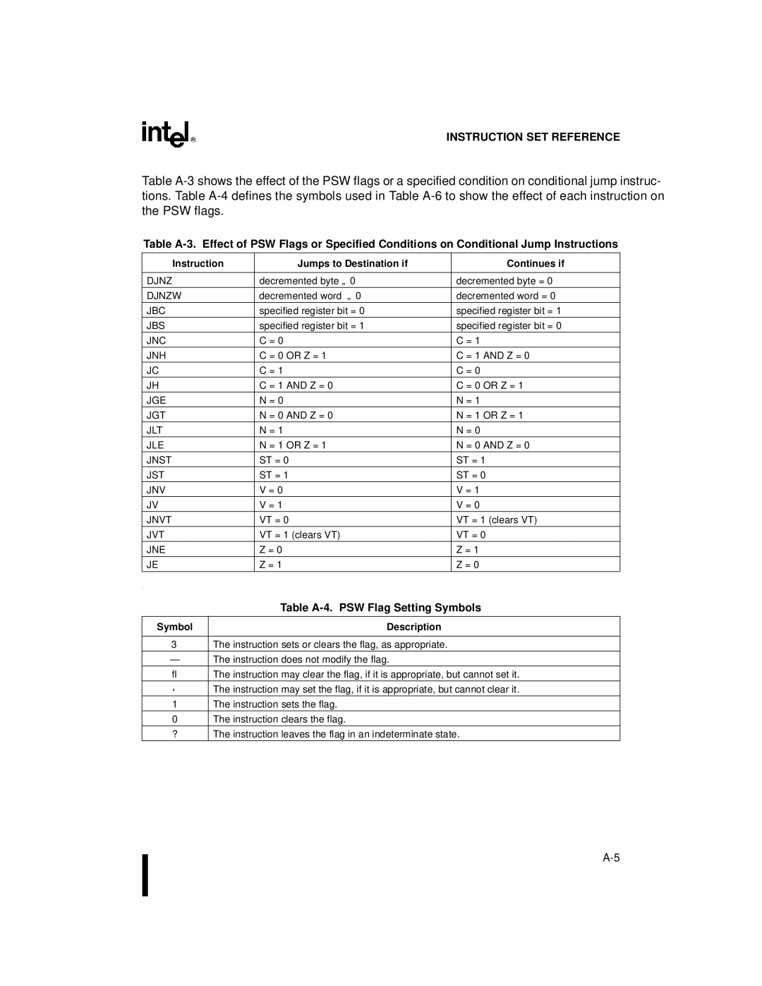
Instruction Set Reference
Page
Appendix a Instruction SET Reference
Table A-1. Opcode Map Left Half
Opcode
Table A-1. Opcode Map Right Half
Value of Bits Shifted Off
Table A-2. Processor Status Word PSW Flags
Mnemonic Description
Instruction Quotient Stored Flag Set if Quotient is
Symbol Description
Table A-4. PSW Flag Setting Symbols
Instruction Jumps to Destination if Continues if
Table A-5. Operand Variables
Variable Description
Mnemonic Operation
PSW Flag Settings
Table A-6. Instruction Set
C V VT ST
Dest ← Dest and SRC
Instruction Format
Andb
PTRS, Cntreg
Dest
Mnemonic Operation Instruction Format
Count ← Count
PC ← Dest
Clear WORD. Clears the value
Compare BYTES. Subtracts the source
Dest MOD SRC
← Dest MOD SRC
Djnz Decrement and Jump if not Zero
Dpts Disable Peripheral Transaction
Djnzw Decrement and Jump if not Zero
Dstptr ← Ptrs + Dstptr ← Srcptr Ptrs ← Srcptr +
Ebmovi Extended Interruptable Block PTRS, Cntreg
Count ← Cntreg
EBR
Onto the stack, then adds to the program
Epts Enable Peripheral Transaction
SRC, Dest
EXT SIGN-EXTEND Integer Into Long
Extb SIGN-EXTEND SHORT-INTEGER Into
Increment WORD. Increments the value Word operand by
JGE Jump if Signed Greater than or
JLE Jump if Signed Less than or Equal
Negative flag is set, this instruction adds
JNV Jump if Overflow Flag is Clear
Jnvt Jump if OVERFLOW-TRAP Flag is
JVT Jump if OVERFLOW-TRAP Flag is SET
Kbyte mode
Mbyte mode
MUL
Mulb
Mulu
NEG
Dest ← Dest PSW Flag Settings
Mulub
Negate INTEGER. Negates the value
Dest ← not Dest
Dest ← Dest or SRC
INTMASK1/WSR ← SP
PSW/INTMASK ← SP
SP ← PSW/INTMASK PSW/INTMASK ←
SP ← INTMASK1/WSR INTMASK1 ←
Scall
Wreg,#count
SHR
Range of 0 to 31 1FH, inclusive. If
Shral Arithmetic Right Shift Double
Shrl Logical Right Shift DOUBLE-WORD
Skip
Rightmost operand
SUB
Subc
Subb
Subc Subtract Words with Borrow DEST, SRC
Subcb Subtract Bytes with Borrow DEST, SRC
Tijmp TBASE, INDEX, #MASK
Index and #MASK = Offset × Offset + Tbase = Dest PC ← Dest
SRC
XOR
Dest ← Dest XOR SRC
Clrb Notb Negb
Table A-7. Instruction Opcodes
Hex Code Instruction Mnemonic
Decb Extb Incb Shrb Shlb Shrab
Hex Code
Instruction SET Reference
8XC196NP, 80C196NU USER’S Manual
ST Direct
ELD Indirect
Arithmetic Group Direct Immediate Indirect Indexed Mnemonic
Table A-8. Instruction Lengths and Hexadecimal Opcodes
Subc Subcb
Logical Direct Immediate Indirect
Opcode Length
Stack Direct Immediate Indirect Indexed Mnemonic
POP Popa Popf Push Pusha Pushf
Ebmovi ELD Eldb EST Estb
Data Direct Immediate
Extended
Direct Immediate
Call Direct Immediate
Jump Direct Immediate
EBR Ejmp
Lcall RET
Djnz Djnzw JBC
JGE JGT JLE JLT JNC JNE JNH Jnst JNV Jnvt JST JVT
Special Mnemonic Direct Immediate Indirect
Shift Mnemonic Direct Immediate Indirect Indexed
Length Opcode
PTS
Normal Autoinc Short Long Reg Mem
Table A-9. Instruction Execution Times in State Times
Arithmetic Group Indirect
Mem Reg
DIV Divb Divu Divub
Mnemonic Direct Immed Normal Autoinc Short Long Reg Mem
Logical
Normal Autoinc Short
Stack Register Indirect
Reg Mem
Indexed Mnemonic
Data Mnemonic Extended-indirect Normal
Extended-indexed
Autoinc Short Long Reg Mem
Mnemonic Direct Immed
Ljmp Sjmp Tijmp
Indirect Indexed Mnemonic Direct Immed
Autoinc Short Long
Shift
Conditional Jump
Mnemonic Short-Indexed
Mnemonic Direct
NOP RST Setc Skip
Special Mnemonic Direct Immed Indirect Indexed
Clrc Clrvt Idlpd
Immed Indirect Indexed
Page
Signal Descriptions
Page
Functional Groupings of Signals
Table B-1 XC196NP and 80C196NU Signals Arranged by Function
Figure B-1 XC196NP 100-lead Sqfp Package
X8XC196NP
Figure B-2 XC196NP 100-lead QFP Package
Figure B-3 C196NU 100-lead Sqfp Package
X8XC196NU
Figure B-4 C196NU 100-lead QFP Package
Table B-2. Description of Columns of Table B-3
Signal Descriptions
Table B-3. Signal Descriptions
Column Heading Description Name
Byte High Enable†
WRH# BREQ#
EXTINT30
VSS
PLLEN1 PLLEN2
VSS if either of the following conditions are true
Asserted only during external memory writes
RESET# NP/NU
Default Conditions
Table B-4. Definition of Status Symbols
RESET#
ALE WK0
Ready WK1 RESET# RPD
WK1 EPORT.30
BHE# WK1
Registers
Page
CPU EPA
Chip Configuration
Table C-1. Modules and Related Registers
Interrupts
Table C-2. Register Name, Address, and Reset Status
EPA3TIME
EPA3CON
EPA2TIME
1FD6H Xxxx P1REG
Xxxx Spbaud
WSR1 NU
ACC0x
Table C-3. ACC0x Addresses and Reset Values
ACC0x
Accstat
Table C-4. Effect of SME and FME Bit Combinations
ADDRCOMx
Table C-5. ADDRCOMx Addresses and Reset Values
Addrcom Address
ADDRMSKx Address Table C-6 Reset State
Table C-6. ADDRMSKx Addresses and Reset Values
ADDRMSKx
BUSCONx
Table C-7. BUSCONx Addresses and Reset Values
Buscon Address
CCR0
CCR1
CONREG0
Epdir
PIN3 PIN2 PIN1 PIN0
Epmode
Eppin
XXH
Epreg
X0H
Epamask
Epapend
Epapend
EPAxCON
EPA xCON Address
EPAxCON Address Table C-8
Bit Function Number
Table C-8. EPAxCON Addresses and Reset Values
Table C-9. EPAxTIME Addresses and Reset Values
EPAxTIME
Intmask
FF203EH EXTINT3
INTMASK1
FF203CH EXTINT2
Intpend
INTPEND1
Ffffh
Onesreg
Onesreg
150 One These bits are always equal to Ffffh
XDIR Address
Table C-10. PxDIR Addresses and Reset Values
PxDIR
PIN7 PIN6 PIN5 PIN4 PIN3 PIN2 PIN1 PIN0
Table C-12. Special-function Signals for Ports
Table C-11. PxMODE Addresses and Reset Values
PxMODE
XPIN Address
Table C-13. PxPIN Addresses and Reset Values
PxPIN
Bit Number
PxREG Address Table C-14
Table C-14. PxREG Addresses and Reset Values
PxREG
P1REG 1FD4H FFH P2REG 1FD5H P3REG 1FDCH P4REG 1FDDH
PSW
PSW
PSE
PSW
Ptssel
Ptssrv
FF200AH EXTINT1
Table C-15. PWMxCONTROL Addresses and Reset Values
PWMxCONTROL
Sbufrx
Sbufrx
Data Received
Sbuftx
Sbuftx
Data to Transmit
Xxxxh
Spbaud
Baud Rate Spbaud Register Value Note Error Mode
Spcon
Spstatus
T1CONTROL
T2CONTROL
Table C-17. TIMERx Addresses and Reset Values
TIMERx
Timer Address
Register Memory 00E0-00FFH
WSR
Byte Windows
Mnemonic Location
Register Memory 00E0-00FFH 00C0-00FFH
P4DIR 1FDBH 7EH 00FBH 3FH 00DBH 1FH P4MODE 1FD9H
TIMER1 †
TIMER2 †
PWM1CONTROL 1FB2H 7DH
WSR1
Register Memory 0060-007FH 0040-007FH Mnemonic Location
0060-007FH 0040-007FH Mnemonic Location
Spbaud 1FBCH 7DH
PWM0CONTROL 1FB0H 7DH
Sbuftx 1FBAH 7DH
Spcon 1FBBH 7DH
Zeroreg
Zeroreg
150 Zero This register is always equal to zero
Page
Glossary
Page
Glossary
DOUBLE-WORD
FET
ISR
PIC PLL
PTS
SFR
Uart
Index
Page
Index
Index-2
Index-3
Index-4
Index-5
Index-6
Index-7
Index-8
Index-9
Index-10
Index-11
Index-12