J2-Super Series
Safety Instructions
To prevent electric shock, note the following
HC-SFS81
Additional instructions
COM
Wiring
RA EMG 24VDC
Usage
Maintenance, inspection and parts replacement
For Maximum Safety
EMC directive
Configuration
Low voltage directive
Machine directive
Wiring
Power supply
Grounding
Auxiliary equipment and options
Use UL/C-UL standard-compliant products
Memo
Contents Functions and Configuration
Operation
Servo Configuration Software
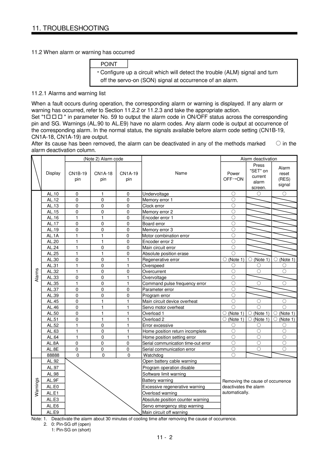
11.2
11.1
12.1
12.2
13.2
13.1
13.3
13.4
15-14
15-11
15-16
15-18
Page
Memo
Introduction
Functions and Configuration
Function block diagram of this servo is shown below
Function block diagram
Stop
Operation using external input signals
System configuration
Operation using external input signals and communication
External I/O signals Servo amplifier axis
Operation using communication
Functions and Configuration
3 I/O devices
Servo amplifier standard specifications
Weight
Other functions Structure Ambient Temperature
Phase pulse Dog cradle type
Humidity
Function list
Model code definition Rating plate
Combination with servo motor
Model
Structure 1.6.1 Part names MR-J2S-100CL or less
MR-J2S-200CL MR-J2S-350CL
Output analog monitor data Encoder connector CN2
Backup Battery holder
MR-J2S-500CL
Name plate Main circuit terminal block TE1
MR-J2S-700CL
Brake option and servo motor
For MR-J2S-500CL
For MR-J2S-700CL
No-fuse breaker
For 3-phase 200V to 230VAC or 1-phase 230VAC
Cables
Magnetic contactor Section Manual pulse generator
Magnetic contactor
For 1-phase 100V to 120VAC
FR-BAL
MRZJW3
SETUP151E
Servo configuration software
Command device Junction terminal Servo amplifier Block
Installation
Installation
Control box 10mm 0.4 in. or more 40mm Or more
Others
Installation of two or more servo amplifiers
Keep out foreign materials
Cable stress
Signals and Wiring
Signals and Wiring
Standard connection example
Signals and Wiring
Internal connection diagram of servo amplifier
Signal arrangement
I/O signals Connectors and signal arrangements
CN1A OPC
DOG COM SON CN2 MDR MRR
Input devices
Signal devices explanations O devices
DOG
ST2
OFF
Proportion control
DI3 DI2 DI1 DI0
Proportional type
Than the rated by the analog torque limit TLA
Temporary
Multiplication Parameter No.1 setting
Stop/Restart Turn it on again to make a restart
Is ignored
MBR
Output devices
Output signal
Input signal
Refer to for the communication function
Communication
3ms or less
OFF
Movement complete
Override VC
Override
Override selection OVR
Used to make the override VC valid or invalid
Internal torque limits 1
Torque limit
Analog torque limit TLA
TL2
External torque limit offset parameter No.26
Parameter No Parameter No
Parameter No TLA
Instantaneous power failure
Regenerative alarm
Overcurrent, overload 1 or overload
Incremental system
CN1A CN1B 24VDC VDD COM
Interfaces 3.6.1 Common line
OPC MR-HDP01 Ppnp
TXD L
Digital input interface DI-1
Detailed description of the interfaces
Digital output interface DO-1
Encoder pulse output DO-2 Open collector system Interface
Lamp load
Output pulse
COM 24VDC VDD VDD-COM
Input impedance 10 to 12k
Analog input
Analog output
Source input interface
Nfbmc
For 3-phase 200 to 230VAC power supply
EMG SON VDD COM ALM
For 1-phase 100 to 120VAC or 1-phase 230VAC power supply
50/60Hz Phase 100 to 120VAC
11, L Control circuit power supply Phase 200 to 230VAC
Terminals
Refer to Sections 14.1.2 and 14.1.3 for details
Timing chart
Power-on sequence Power-on procedure
Forced stop
VDD COM EMG
Connection diagram
HA-FF053 B to 63 B
HC-MF053 B to 73 B
HC-UF13 B to 73 B
HC-SF121 B to 301 B
Earth
3 I/O terminals HC-KFS HC-MFS HC-UFS3000r/min series
MDR MRR BAT
HC-SFS HC-RFS HC-UFS2000 r/min series
COM MBR 24VDC
Setting
Coasting Servo motor speed Min 60ms Base circuit
Both main and control circuit power supplies off
Alarm occurrence
CN1A CN1B
NH1 Nichifu
Servo amplifier terminal block TE2 wiring method
JST
CRIMPFOX-UD6
Torque screwdriver
Instructions for the 3M connector
N6L TDK
Nakamura Seisakusho
Before starting operation, check the following
Operation
Machine
CDV
Machine conditions
Function selection Absolute position detection system
Startup procedure
Program end
ZRT
Home position return
Program operation mode What is program operation mode?
Programming language
Command list
Tripi
Trip
ITP
Lpos
For
TIM
Times
Details of programming languages
TIM Dwell command time 100 ms MOV Absolute move command 2000
500 r/min STC
200 ms MOV Absolute move command
Absolute continuous move command
Continuous move command Mova Movia
Incremental move command
Incremental continuous move command
Outon
Mova Absolute continuous move command STM m
OUT1 OFF
OUT1 is turned off in 200ms
300 MOV Absolute move command 1000 10STM
OUT2 is turned off in 100ms
OUT3 is turned off in 500ms
Outof
Trip Absolute trip point 250
Tripi Incremental trip point 300
OUT2 OFF
MOV cannot be used with Tripi
300 Movi Incremental move command
Tripi Absolute trip point 300
Program output 3 OUT 3 is turned OFF
Movi Incremental move command 500 r/min
TIM Dwell command time 200 ms SPN
OUT1
PI1 OFF
ITP Interrupt positioning command 200
Interrupt positioning command ITP
Trip Trip point 500
Count
Count
Waiting for PI1 to be turned on by SYNC1 a
Step repeat command end For
Step repeat command for Next
Step repeat command end
Next
Times
Current position latch is set
Position latch Lpos
Movi R2
Movi R1
Parameter
Basic setting of signals and parameters
CCW rotation with
Position data Initial value 100 1000
100 ms MOV Absolute move command 5000
Program operation timing chart Operation conditions
100 ms MOV Absolute move command 2500
SPN Speed Motor speed 1000 r/min STC
Jog operation Setting
Manual operation mode
Servo motor rotation direction
ST1ON ST2ON CCW
PED OFF
Manual pulse generator multiplication
Manual pulse generator operation Setting
10 m
100 m
Parameter No.1 setting valid Time Times
Length of the proximity dog
Manual home position return types
Since the machine part collides with
Instructions
Home position return parameter
Set the input signals, parameters and program as follows
Signals, parameters
Dog type home position return
Length of proximity dog
Adjustment
Count type home position return
Set the input signals and parameters as follows
Movement over the moving distance
Return is selected
Data setting type home position return
Is obtained to output home position return
Stopper type home position return
Completion ZP
Set the input signals and parameter as follows
Signals, parameter
Dog type rear end reference home position return
Set the input signals and parameters as indicated below
Count type front end reference home position return
Dog cradle type home position return
Phase signal position
Software limit cannot be used with these functions
Home position return automatic return function
Absolute position detection system
Specifications
Restrictions
Structure
Servo amplifier Program No. selection DI0 to DI3, etc
Outline of absolute position detection data communication
CON1
Parameter setting
Positioning operation in accordance with programs
Serial communication operation
Selection of programs
Multidrop system
Group designation
Group setting example
Station
Group setting instructions
Commands
Incremental value command system
MOV
Mova
Program example
Parameters
Item list
List
FFC
SIC
TLO
TL1
NH2
NH1
LPF
PG2B
Detail list
Command system, regenerative brake option selection 0000
Multiplication factor Function Column
85Hz
Refer to Chapter
High
CMX CDV PED
MOD Analog monitor output
Communication conditions, and clear the alarm history
Monitor 2 MO2. Refer to Section
Status display on servo amplifier display
Setting s
No time-out check Time-out check period setting
19 *BLK Basic parameters 20 *OP2 22 *OP4
Operation can be performed for the parameters marked
Used to set the offset voltage to analog override 999
999 to
65535
Pulses/rev Set value
ZTT
DCT
Parameter error
OP9 Function selection
Setting
OPA Function selection a 0000
Connector pins
Machine resonance suppression filter 0000
0000 Don’t change this value by any means
Used to selection the machine resonance suppression filter
Used to set the machine resonance suppression filter
63 LPF Expansion parameters 64 GD2B 65 PG2B 66 VG2B
Changing is valid. Made valid when auto tuning is invalid
Low-pass filter/adaptive vibration suppression control 0000
Control. Refer to Chapter
CDS
68 *CDP
Gain changing selection 0000
BIN HEX
0001 0209 060A 1918 030B 0504 0102 0000 0005 120E
Machine specifications Ballscrew lead Pb 10 0.39 mmin
Guideline for setting the electronic gear is
Reduction ratio n Servo motor resolution Pt Pulse/rev
Machine specifications Pulley diameter r 160 6.30 mmin
Changing the status display screen
Change the following digits of parameter No.17
Pattern acceleration/deceleration
Contents of a setting
Alarm history clear
Changing the stop pattern using a limit switch
Software limit
Memo
System configuration Components
Servo Configuration Software
MR-CPCATCBL3M
For use of RS-232C
Configuration diagram
For use of RS-422 Up to 32 axes may be multidropped
CN3 CN2
Station number setting
Station setting
Closing of the station setting window
Click the Close button to close the window
Parameter value write a
Parameters
Parameter value verify b
Parameter value batch-read c
Parameter default value indication g
Parameter value batch-write d
Parameter change list display e
Simple Program 6.5.1 Program data
How to open the setting screen
Explanation of Program Data window
Explanation of Program Edit window
Servo Configuration Software
Explanation of Indirect Addressing window
Indirect addressing
Limited number of time to write to EEP-ROM is 100,000
Servo Configuration Software
Device assignment method
When using the device setting, preset 000E in parameter No
Screen explanation
Servo Configuration Software
Servo Configuration Software
Point
Acceleration/deceleration time constant setting b
Servo motor speed setting a
Servo motor start c, d
Servo motor stop e
Positioning operation
Servo motor start d, e
Moving distance setting c
Temporary stop of servo motor f
Positioning operation window closing g
Click Close to close the window
Click Start to perform motor-less operation
Signal ON/OFF setting a, b
Output signal do forced output
Do forced output window closing c
Program of the MR-J2S-CL can be test-operated
Program test operation
Closing the Program Test window b
Displaying the program a
Click the OK button to close the Program Test window
Alarm history display
Alarm history
Alarm history clear a
Closing of alarm history window b
Memo
Display and Operation
Display flowchart
Display transition
Status display
DOW
Following table lists display examples
Display examples
Following table lists the servo statuses that may be shown
Status display list
Down
Diagnosis mode 7.3.1 Display transition
Diagnosis mode list
Display and Operation
Alarm mode
Indicates no occurrence of an alarm
Alarm mode list
Display and Operation
Parameter mode transition
Parameter mode
Operation example Parameter of 5 or less digits
Signed 5-digit parameter
Segments of the seven-segment LEDs correspond to the pins
External I/O signal display
Display definition
CN1A CN1B CN1B
Press UP twice Press SET for more than 2 seconds
Mode change
Termination of jog operation
How to use the buttons is explained below
How to use the keys is explained below
Termination of motor-less operation
To terminate the motor-less operation, switch power off
Memo
Gain adjustment mode explanation
General Gain Adjustment
Adjustment using servo configuration software
Adjustment sequence and mode usage
You can automatically set the optimum gains
Executing gain search under to-and-fro
Position control gain
Auto tuning Auto tuning mode
Speed control gain
Block diagram of real-time auto tuning is shown below
Auto tuning mode operation
PG1,VG1
PG2,VG2,VIC
Adjustment procedure by auto tuning
Response level setting in auto tuning mode
Operation of manual mode
Manual mode 1 simple manual adjustment
Adjustment by manual mode
Adjustment procedure
For position control
General Gain Adjustment
Adjustment procedure
Interpolation mode
Adjustment description
PG2
100Hz 105Hz 130Hz 160Hz 200Hz 240Hz 300Hz
Auto tuning selection
Memo
Machine resonance suppression filter Function
Special Adjustment Functions
Deep 40dB 14dB 8dB Shallow 4dB
Parameter No Notch frequency
Adaptive vibration suppression control Function
Set the operation of the low-pass filter parameter No
Low-pass filter Function
Applications
Gain changing function
GD2B
Gain changing selection parameter No
Parameters No , 34 to
Gain changing condition parameter No
Gain changing time constant parameter No
When you choose changing by external input
This operation will be described by way of setting examples
Setting
Gain changing operation
Speed integral compensation 250 Changing ratio
When you choose changing by droop pulses
Gain changing selection 0003
Gain changing condition Pulse
Memo
Inspection
Inspection
Life
Years
Memo
Position control mode Troubleshooting
Troubleshooting
Trouble at start-up
Make operation instable
Alarms and warning list
When alarm or warning has occurred
MR-J2S- CL
MR-J2S
Option, change regenerative brake
Reexamine acceleration
Option
Capacity of built-in regenerative
Review environment so that ambient
Servo motor locked Input terminals U, V, W
AL.50 Overload Load exceeded
Serial Communication cable fault Repair or change the cable
Remedies for warnings
Memo
TE1 TE2
Outline Dimension Drawings
TE1
MR-J2S-70CL MR-J2S-100CL
PE terminal Fan air orientation Servo amplifier Weight
Mounting hole Unit 1305.12 2007.87 1184.65 Terminal layout
Mounting hole 1807.09 1606.23
Insulation displacement type
Connectors Servo amplifier side 3M
Soldered type
Threaded type
DE-C1-J6-S6 34.5 24.99 #4-40
Communication cable connector JAE
Memo
Overload protection characteristics
Characteristics
MR-J2S-10CL to MR-J2S-100CL MR-J2S-200CL to MR-J2S-350CL
HC-MFS053 HC-UFS13 HC-KFS23
HC-KFS053
HC-MFS23 HC-UFS23 HC-KFS43
HC-MFS43 HC-UFS43 MR-J2S-60CL HC-SFS52 HC-SFS53 HC-KFS73
Heat dissipation area for enclosed servo amplifier
Temperature distribution in enclosure
There is internal relay delay time of about 30ms
Dynamic brake characteristics
Mmin
Mm/minin/min
HC-SFS1000r/min series
HC-KFS series
HC-SFS3000r/min series
HC-MFS series
MR-J2S-500CL MR-J2S-700CL
Encoder cable flexing life
MR-JCCBL M-H MR-JHSCBL M-H MR-ENCBL M-H
MR-JCCBL M-L MR-JHSCBL M-L
MR-J2S-40CL 60CL 30A
MR-J2S-10CL 20CL 30A
Attenuated to approx a in 0.5 to 1ms
MR-J2S-70CL 100CL 54A
Memo
Selection of the regenerative brake option
Options and Auxiliary Equipment
100 300 500
130 300 500
Servo amplifier Inverse efficiency% Capacitor chargingJ
1047
Set parameter No.2 according to the open to be used
Connection of the regenerative brake option
For the MR-RB50 install the cooling fan as shown
Mounting method
For the MR-RB50 MR-RB51 install the cooling fan as shown
MR-RB032 MR-RB12
Outline drawing
MR-RB32 MR-RB30 MR-RB31
119
12.3
MR-RB50
Selection
Brake unit
FR-BU-15K
16.5 MR-J2S-500CL FR-BU-30K
Brake unit FR-BU
Outside dimensions
Unit mmin
FR-RC15
Resistor unit FR-BR
FR-RC30
RDY
FR-BAL VDD COM EMG ALM SON
FR-RC
RA2 EM1 OFF
Mounting hole machining dimensions
Outside dimensions of the power return converters Unit mmin
HC-KFS
Cables and connectors Cable make-up
MR-JCCBL M-H
MR-JCCBL M-L
MR-JHSCBL M-L
JAE
MR-J2TBL
MR-J2CN1
MR-TB20
MR-J2CN3TM
16.4
Standard flexing life Long flexing life
131.2
164.0
MR-JCCBL10M-L MR-JCCBL10M-H MR-JCCBL30M-L MR-JCCBL50M-H
MR-JCCBL2M-L MR-JCCBL5M-L MR-JCCBL2M-H MR-JCCBL5M-H
MRR MDR BAT
SHD
MR-JHSCBL M-L
MR-ENCBL50M-H
Communication cable
Connection diagram
Model MR-CPCATCBL3M
MR-CPCATCBL3M
Junction terminal block MR-TB20
How to use the junction terminal block
Terminal labels
MR-J2TBL05M
DI0 PED ST1
Junction terminal block cable MR-J2TBL M Model MR-J2TBL M
LSP LSN ALM
B10
MR-J2HBUS CN3B CN3A CN3C
Maintenance junction card MR-J2CN3TM Usage
CN3A CN3B CN3C
VDD COM EM1
MR-J2HBUS05M MR-J2HBUS1M MR-J2HBUS5M
Bus cable MR-J2HBUS
External digital display MR-DP60
When using the MR-DP60, set 1 4 in parameter No
Terminal arrangement
Start bit Date bit
Mounting
Outline dimension drawing
VDD CN1B OPC CN1A
Manual pulse generator MR-HDP01 Specifications
Battery MR-BAT, A6BAT
Recommended wires
Recommended wires Wires for power supply wiring
Auxiliary equipment
MR-J2S-10CL MR-J2S-20CL MR-J2S-40CL AWG14 a 25 AWG16 a
Wires for option cables
Wires for cables
Recommended crimping terminals
AMP
No-fuse breakers, fuses, magnetic contactors
Power factor improving reactors
MR-J2S-20CL
MR-J2S-40CL 20CL1
Following relays should be used with the interfaces
Relays
Surge absorbers
Noise reduction techniques
Noises produced by servo amplifier
10 to 100MHz 100 to 500MHz 150
Noise reduction products
Ex A.2003
Outline drawing
Outline drawing Unit mm Unit FR-BLFMR-J2S-350CL or more
NV-SW
Leakage current breaker Selection method
NFB
HC-MFS73
Selection example
Combination with the servo amplifier
EMC filter
NFB Line Load
HF3040A-TM 260 210 155 140 125
HF3040-TM HF-3050A-TM
R3.25
HF3050A-TM 290 240 100
WA2WYA2SEBK2KΩ Japan Resistor make
Memo
Cable connection diagram
Configuration 15.1.1 RS-422 configuration Outline
Wire as shown below
Communication Functions
Single axis of servo amplifier is operated
15.1.2 RS-232C configuration Outline
Description
Communication specifications 15.2.1 Communication overview
MSB
Serial communication baudrate
Serial communication response delay time
Serial communication selection
Protocol station number selection
Transmission of data from the controller to the servo
Protocol
Data length depends on the command
Recovery of communication status by time-out
Data frames
For example, 61H is transmitted in hexadecimal for group a
Ascii codes are used
Checksum
Error codes
SOH
Retry operation
Time-out operation
Initialization
Communication procedure example
Data item Value Description
STX ETX
Read commands Status display Command
Command and data No. list
Parameter Command
External I/O signals Command
Current alarm Command 02
Alarm history Command
General-purpose register Rx value Command 6D
Current position latch data Command 6C
General-purpose register Dx value Command 6E
Group setting Command 1F
External I/O signal Command
Write commands Status display Command
Current alarm Command
General-purpose register Rx value Command B9
Operation mode selection Command 8B
External input signal disable Command
Data for test operation mode Command 92 A0
Group setting Command 9F
Processing the read data
Detailed explanations of commands 15.12.1 Data processing
Writing the processed data
Status display Status display data read
Command Data No
Status display data clear
1EA5
Parameter Parameter read
Command Data No Data No. definition
Parameter write
Command Data No Set data
00 to See below
External input pin status read
Reply ON/OFF statuses of the input pins are sent back
CN1B-18
External output pin status read
CN1A-14
Device ON/OFF
Read of the statuses of output devices
Ready RD Limiting torque TLC Trouble ALM
See below
Signal Status
Disable/enable of I/O devices DIO
Enable
Input devices DI
See below
Input devices ON/OFF test operation
1EA5 Choose the test operation mode
Test operation mode Instructions for test operation mode
Cancel the test operation mode
Enable the disabled input devices
LSN and ST1 Reverse rotation start Turns on SON
Forward rotation start Turns on SON
LSN and ST2 Stop Turns on SON LSP and LSN
Servo-on Turns on SON LSP LSN Stroke end OFF
Communication Functions
Choosing do forced output in test operation mode
Output signal pin ON/OFF output signal do forced output
External output signal ON/OFF
Command Data No Setting data
For example, 0032 means A.32 and 00FF A. no alarm
Alarm history Alarm No. read
Alarm occurrence time read
Erase the alarm history Send command 82 and data No
Read of the status display at alarm occurrence
Current alarm Current alarm read
Current alarm clear
Current position latch data
Send command 6C and data No to be read
Transmission
Reply
General-purpose register Dx read
General-purpose register General-purpose register Rx read
General-purpose register Dx write
General-purpose register Rx write
Group setting read
Group setting write
Reply Slave station sends back the group setting requested
Servo amplifier group designation
Reply Slave station returns the software version requested
Software version
Appendix
App 1. Status indication block diagram
App
For CN1B
Appendix
Manual number is given on the bottom left of the back cover
Revisions
Model Code