Page
Page
Table of Contents Section Descriptionpage
Feature Description
Feature Access Codes
Regulatory
Section Glossary of Abbreviations
Feature
Section
140
DSS/BLF
100-2 Two Line
Dssiblf Console. The Transfers may be
MEL Issa SEP MON
Multiline Terminals 100-5
While they
Talking
Away from Their
Ability Set Call
Chapter
LED
Night Mode
External Tone Ringing four tones is
External Zone Paging with Meet ME
Holding
ETE-6- LED is red, while at other stations it will Remain
Handsfree Dialing and Monitoring
Hold Exclusive and NON-EXCLUSIVE
Function of the Electra Mark11 System which
Station user dials the number indicated. Once
Electra MarkII’s trunks to meet almost any
Internal Zone Paging with MEET-ME
Such
Provide Auto Answer
By an SLI-E ETU port, a Multiline
Terminal With LCD equipped with a DTA-E Unit
APRIL,1990
100
TRUNK/MFR Test and Busy OUT Attendant
Chapter
150
LCD Indications
Conference LK16 TR Cocall LK16 NE1L.A
Error
Not Install
LCD Indications
Code
Section Feature Access Codes Numbering Plan
SLT
Feature Condition Code
Section Equipment Identification
General Information
Equipment Description
This power supply accepts a DC input voltage
PSE-DD-1 PSU
RSG-E Unit
RAA-E Unit
CBL-E Unit
COI-E ETU
COI-EB ETU
TLI-E ETU
SLI-EB ETU
MFR-EA ETU
CNF-E ETU
ECR-E ETU
ND-29292
HFU-E Unit
DPA-E Unit
ADA-E Unit
ADA-ER Unit
Hardware Installation
Chapter Table of Contents
Section Specifications
Programming Station
200-3
To determine
An ESE-32B-1 CCU is always required ESE-32E-1 CCU
PSE-AD-l, PSE-DD-1 PSUs
MFR-EA
CNF-E
ECR-E
VMI-E
Power Requirements
NC = Not connectable
By an
= Compatible with other
Electra Mark11 capacities are as follows System Ports
Intercom paths Multiline Terminals
110
Buffers
Expansion
Basic
Expansion CCUs
220.10
RAA-E
RSG-E
ZOO-8
PCM
Dialing Specifications
Battery Backup
Smdr
CO/PBX
On DND
OFF
DSS KEY
LED OFF
Site Preparations and MDFlIDF
Construction
Main Distribution Frame MD!? consists of two
Parallel
Practice generally results
Station Equipment
KEY
Por4Relatior
@ee
Central Control Units CCUs
They can operate as
MDF Co3
TIP
J8 AC OUT
Floor Mounting the CCU
#!9
15 Floor Mounting 4 CCUs 200
Or Higher
Common Control
CPU-EB CPU-EC
Level ETU
18 TSW-E Switch Layout 200
CPU-EC ETU DIP Switch
TSW-EB ETU
MMC-E ETU
CPU-E
Odb
On = 2db
ON=
4db
ESI-EA/EB ETU
SLI-EA/EIB ETU
MFR-EA ETU
MON
SW1
24 SMDR-E ETU Switch Layout
200-26
LCR-EETU
200-29
PIN # Function
OGC
ICC
OTC
ITC
30 LCR-E ETU DIP1 Switch
Figure ZOO-29 Smdr
Section Power Supply Installation
Green
Section Ancillary Device Connection
’7 Interconnection of PSE-DD-1 PSU
= Compatible
Ancillary Device
Ancillary Devices HFU-E ETU DPA-E ETU ADA-E ETU DTA-E ETU
I260.2. Handsfree Unit HFU-E
Ancillary Device Adaptor UNIT. ADA-E
Data Terminal Adaptor Unit DTA-E
45 DTA-E Unit 200
Reinstall the two screws and designation strip 200
DTA-E Installation
Wall Mount Unit Installation
Switch Assignment
SW3
CTS
Figure ZOO-47
Music on Hold
Background Music / Delay Announcement
External Paging
External Tone Ringing / Night Chime
Offoff Offon Onoff Onon
Installation
Electra MARK11
Modem Termination
To pins
Feet Max
On both Ends
Shown in Figure
RS-232C Male Connector
Chapter
Page
Table of Contents
Programming
III
RAA SLT
Charts
350 Function
360 Code/Call Restriction
HOW to USE TR’I~~BA~-X~.~+M
Reader directions and recommendations for using Chapter
’ 310 General
+ dialing areas Direct Dialing areas
Memory Memory Feature Feature Section Item
DEtlGNAGNNl-5 A--E l-10 Feature KEY Fl-F5
300-2
Resident SY I’EM Default Values Memory Function
1ECTION330
Values Block
=CO/PBX
Default Values
Function Default Values
Function Default Values
None
TLI-II
TIE Line
Memory Function Default
Block
This page Left Blank Intenionally
Program Mode
OFF-LINE
Terminal
INE Assign
Guide to Feature Programming
General Information Line KEY Assignment
3B9,3B10,4B4
System. Each Other than PE i
Line Program Mode Terminal DAY
Memory Block 1B Ringing Assignment
Ring DAY
TEL105
Guide to Feature Programming
General Information Ringing Assignment
1D3,2D2
Line Program
Terminal DSS/BLF ATT
7DSS ATT
Dssi Vacant DSS ATT
Information
Assignment
General
DSS/BLF to Attendant
F Line Program Mode TERMINALDSS/BLF BLF T E L Assign
Go off line Depress Fl, then F8 Depress F12
General Information BLF Terminal Assignment
LE2
KFY FI JNC Tion OFF Linf
Feature OW6 Vacant Dssi ZONE?? DSS ROW1
PROGRAMMODE1 TERMINALDSS/BLF Dssdss KEY Devi CE? Dssi
DSS OWI TEL
Feature Station Appearance
General Information
DSS/BLF Button
2ClO
F Line Program Mode Terminal
Dssi FLX Feature
ZONE?? DSS X . Feature MSG Wait
FLX Feature FLX2
General Information Dswblf Flexible Function KEY Assignment
1Cl
2A7
KFY Function OFF 1 INF
Memory Block 1CS DSS to CO ADD-ON Module Assignment
F Line
Terminal DSS/BLF
Admodule
General Information Dssto CO ADD-ON Module Assignment
Memory Block lC6 CO ADD-ON Module Line KEY Assignment
DsshL~
ADMOD? Assign Admod OWI
Assign Admod ROW1
LC6
General Information CO ADD-ON Module Line KEY Assignment
LC5 1Cl. lC7 C8.1 E2
KFY FUNfTION fOFF Linfi PKR ON/OFF Line
F Line Program Mode
Memory Block lC7 CO ADD-ON Module DAY Ring Assignment
S / B L-F
DAY RI NG
General Information CO ADD-ON Module DAY
Ring Assignment
LC5.1C6 LC8,lEZ 2D2,3A2
Enter Enter each assignment Backward Decrements row number
Night RNG
Rowz
Admod
LC8
General Information CO ADD-ON Module Night
LCS.lC6 1C . E2
2D&2
F Line Program
PRM RNG Pref
PRM RNG.L.PREF
Prime
Digit Code Feature
KFY Function OFF I INF
All CPU levels. See Step
Data Service Assignment
Line Program Mode Terminal Feature Data Service
Data Term
Depress
Service Assignment
Data
General Information
4B4 287
Memory
User Program Assignment
User Program
User
= Default
General Information User Program Assignment
KFY FI JNfTION OFF LINF! Qpkr ON/OFF Line
Ringing Note Riig
Memory Block lD4 Trunk Group Incoming Restriction
TRK.GINCOM.REST TEL??? TRK.GINCOM.REST TEL104
TRK.G INCOM.REST
Operation q Go off line Depress Fl, then F9 Depress F14
General Information Trunk Group Incoming Restriction f
2Cl2c2
Line Program Mode Terminal Feature RK. G OUTGO.REST
Memory Block lD5 Trunk
Group Outgoing
~.3
General Information Trunk Group Outgoing Restriction
2Cl 2C2,2C3
Terminal Feature
Restriction
Code Restriction
Code REST.#104
General Information Code Restriction Table Access
107 3El.3E2.3E3
3E4,3E7,3E8
3E10,2Cl-2C3
Memory Block lD7 Class of Service Assignment
Classof Service TEL??? CLS.OF
Svc
Svc #lO
General Information Class of Service Assignment
LD7
481 or 4B6
LZDl,ZD2,203 12E1,3B3
Mode Terminal Feature ATT
Memory Block lD8 Terminal to Attendant Assignment
XsXX
Term ATT
WY FUNrTlON cFF I INFj
3A2,3A3,3A4
Spkr ON/OFF Line
Mode Terminal Feature TERM-ZONE Pagi
Paging
Zonex Term
ZONE2 TERM-ZONE Paging
Guide to Feature Programming
General Information Terminalto Paging Zone Assignment
2El
KFY FUNt Uoff
Memory Block lDl0 Call PICK-UP Group Assignment
CALLPICKUP.G TEL??? TEL104-PIC.G?
Call Pick
L 1 OL4 PIC.Gl
General Information Call Pickup Group Assignment
Line Program Mode Terminal Assign
Memory Block 1El Terminal Exchange
TEL104 ? ?
Depress Enter key F-W
General Information Terminal Exchange
LC2,2Al, 3A2
Chapter
Program Terminal TERM.ADD MOD?
TE RM.ADD MOD1 TERM.ADD MOD? Line
Slot
SLOT?
LE2
General Information Terminal ADD Port Equipment
Type
F Line Program Mode Terminal Assign
MOD? Slot
MOD1 SLOT8
IN/OUT
LE3
General Information Terminal Busy Assigni
4E9
TEL
Terminal Assign
Nformat
MOD1
TEL Informat DSS?
General Information TERMINAL/TELEPHONE Information
Clear Enter
Line Program Mode Terminal Assign Port
Memory Block lE5 Port Information
ION
MOD? Slot Port
General Information Port Information
4Cl
KFY Functitn QEF Line
All CPU levels. See Note
Memory Block lE6 Telephone Number Exchange
OFF Line Program
TEL NBR Exchange
TEL??
LE6
General Information Telephone Number Exchange
LC3
Enter Enter each number exchange Backward
Program Mode Terminal Assign TEL NBR Change
Memory Block 1E7 Telephone
Number Change
TEL NBR Change
Change
Telephone Number
ZEl,lC3,2ClO
Ction OFF NF
Digit Rest
DIGIT??
DIG
Digit
II General Information CO Line Digit Restriction
Assignment
ZCl-2C3
DI GIT Rest
FEATURE1
Block 2Al
System
Programmi TEL Number
2Al
General fNFORMATlON Programming Terminal
LE2.4Cl
TEL#
Line Program Mode
SYS FEATURE1
Memory Block 2A2 Speed Dial Tenant Assignment
Code
2A2
General Information Speed Dial Tenant Assignment
OFF Linf
3A4,1D8
Line Program Mode SYS
Memory Block 2A3
Dial Override Assignment
Override TENANT?
General Information Speed Dial Override Assignment
KFY FI JNfTlOhUOFF I Infi $PKR ON/OFF Line
Memory Block 2A4 Incoming Prime Line Pickup
Incom
Operation 1AND -WDISPLAY
PR1ME.L
General Information Incoming Prime Line Pickup
KFY Functuoff
Memory Block 2A5 CO * and # AS First Digit Assignment
Operation 1-AND -wDISPLAY Go off line
To be dialed as a first digit on a CO appearance
Guide TO.FEATURE Programming
Eneral Information CO * and # AS First Digit Assignment
ClLEAR Enter Enter option
All CPU levels
Memory Block 2A6 Smdr Incoming
Smdr
Print Operation Display
F2, then F6
2A6
General Information Smdr Incoming Print
201
YFY FUNCTlQbl OFF L@JF
Line Program Mode SYS FEATURE1 ALL Call
Internal all call feature. See Note 300
Memory BLOCK2A7 Internal ALL Call
Go off line Depress F2, then F6 Depress F17
2A7
General Information Internal ALL Call
Function OFF I INF
TEL# Clear
SYS FEATURE1 Account
Memory Block 2A8 Account Code Digit
DIGIT-XX Account
DIGIT-09
Code Digit
General Information Account
LD7,2Dl 2E1 3B3
FEATURE1 PBX Outgoing
Memory Block ZAS PBX Outgoing Code
Outgoing
PBX Outgoi
2A9
General Information PBX Outgoing Code
4Bl or4B6
KFY Fumtion OFF I INF! Qpkr ON/OFF Line
Digi
Digitxx
DIGIT12
Using Tie Line
General Information TIE Line Digit Restriction Assignment
KEY Function ..UFF 1INF
Program Mode SYS FEATURE2 PC D I AL Assign
Memory Block 2Bl
Modem Pooling Terminal Keyboard Dialing Assignment
2Bl
2Dl
General Information Modem Pooling /TERMINAL Keyboard
Dialing Assignment
‘-A
Memory Block 2B2 Allow Forward OVERRIDE4
AL LOW FWD Over
AL LOW FWD 0 V E R
2B2
General Information Allow Forward Override
QPKR- ON/OFF Line TEL#
Enter Enter assignment B/W
Line Program Mode FEATURE2
Memory BLOCK2B3 DIT Trunk to Tenant Assignment
‘1 ,’
TRUNK?? TRK ANT TRUNK02 Tenantx TRUNK03 Antx
2B3
To Tenant Assignment
General Information Dittrunk
2B4 2C1,2C2,3A4
Program Mode SYS
DAY Mode
Memory Block 2B4 DIT / ANA Assignment
2B4
General Information DIT/ANA Assignment
1D8,2B3,3A4
OFF Line Program Mode
Memory Block 2B5 LCR 1+ Dialing Assignment
+DIAL
LCR
General Information LCR I+ Dialing Assignment
KFY Function
SYS FEATURE2
Memory BLOCK2B6 LCR Local Call Override
LCR L oc Callove
LCR Call OVE
2B6
Ii Generalinformation LCR Local Call Override Assignment
2B5,2B9
S . FEATURE2
Memory Block 2B7 Modem Pool Assignments Operation
Modem Assign
SLT150 RMl
2B7
General Information Modem Pool Assignment
LD2,2Bl
L2D1, 4B4
Memory Block 2B8 VMI Assignment
VMI
LKI-4
Operation 1AND T-WDISPLAY
General Information VMI Assignment
KFY Funcw
Dtmf
Restricted Default Depress Enter Key See Note
Memory Block 2B9 LCR Bypass Assignment
LCR Bypass Line KEY
LCR LED OFF
2B9
General Information LCR Bypass Assignment
LD7 2B5,286
KFY F-OFF
Line Program Mode SYS FEATURE2 Recall
Memory BLOCK2BlO
Recall KEY Operation For TIE Lines
Tone or extension dial tone. See Note 300
General Information Recall KEY Operation for TIE Lines
Function !OFF 1INF
Display Line Program Mode SYS Group Trunk TRUNK.G TRUNK??
Trunk TRUNK.G U N K
2c1
General Information Trunk to Trunk
Group Assignment
Line Program Mode SYS Group Trunk Tenant TENANT? TENANT1
Memory BLOCK2C2 Trunk Group to Tenant Assignment
Trunk Tenant TENANT2
Trunk Groups to the tenant chosen. See Note
2c2
Generalinformation Trunk Group To Tenant Assignment
2Cl
3C2
Memory Block 2C3 Trunk Group to Access Code Group
Liine RIA Mode SYS Group RIK TRK.G-A.C.G TRK.G4
TRK.64
TRK.65
General Information Trunk Group to Access Code Group
Access Accessitem Itemdialcodes Code A.C.G
KFY Functionjoff I INF
M.B El
Memory Block 2C4 Voice Mail Hunt Group Assignment
Generalinformation Voice Mail Hunt Group Assignment
KEY Function OFF Line
After , the display will show any previous assignment
Memory Block 2C5 Delay Announcement Assignment
General Information Delay Announcement Assignment
2C5
3B5-3B8
Enter Enters each assignment Decrements trunk number
SYS Group TRK.A.C.G
A02
General Information Uniform Dial to Trunk Access Code
Trunk Access Code Groups to Various Uniform Dial Numbers
Group Assignment
Memory Block 2C7 Night Chime Assignment
SYS Group
GHT Chime
Night Chime
2C7
Night Chime
2c1 2c9
Assign Trunk Groups to
F -LINE Program Mode
Memory Block 2C8 External Ringing
EXT
EXT INTERVAL2
Generalinformation External Ringing Control Assignment
Interval Numberringing Pattern
Line Program Mode SYS Group Relay Assign
Memory Block 2C9 ECR Relay Assignment
Ight Chime
Ight Chime Asgn
General Information ECR Relay Assignment
LK3
Memory Block
Virtual Extension
ASS
EXTENSION-200
General Information Virtual Extension
LA, 2El
VE48 = EXT
Total number of Virtual 300
Memory Block 2Dl- Time Base Assignment
Line KEY Timer
General Information Time Base Assignment
CPU-EC3
CPU-EC4
Line Program Mode SYS Base Isec Depress KEY
Memory Block 2D2 Time Base Assignment
OUT Base Isec
Talk Start
2D2
1D7,4Bl
2D3, lA
Line Program Mode Base
Memory Block 2D3 Time Base Assignment
OMI Depress KEY
Auto Scon
2D3
General
Information Time Base Assignment Ill
Line Program Mode SYS Access
Code Assignment
ITEM23 Internal
ITEM23 Internal PAG
General Information System Access Code Assignment
2El
KEY Function OFF Linf
Codes Feature
Flexible
Flexible Codes
CPU-EBB
Fixed Codes
Memory Block 3A2 Attendant 3rd and 4th Assignment
ATT3 Asgn Depress
Operation -AND -DISPLAY
Depress F3
General Information AlTENDANT 3rd & qfh Assignment
Memory Block 3A3 Attendant Overflow Assignment
ATT Overflow ATT? ATT2-+ ATT? ATT2-+ ATT4 ATT3-+ ATT?
300-138
Attendant
General Information Attendant Overflow Assignment
Display Shows any previous Assignment
To be set
Overflow is for internal operator Dia .l 01 calls only
Block 3A4 Attendant To Tenant Assignment
ATT1 TE Nanti ATT -T E Nant Asgn ATT2-- Tenantx
N a NLT
ATT Tenant Asgn
Generalinformation AlTENDANT to Tenant Assignment
Sysz FEATURE1
Memory Block 3Bl- First Ring Pattern Assignment
Pattern Depress Line
300-142
3Bl
General Information First Ring PAlTERN Assignment
3B2,4B6
Spkr ON/OFF Line TEL# Forward
Memory Block 3B2 Centrex Ringing Assignment
Centrex Ringing Trunk GROUP?
CTX
Depress Line
382
General Information Centrex Ringing Assignment
4B6 3Bl
Memory Block 3B3 Forced Account Code Digit Assignment
ACC Code
Digits
Forced
3B3
General Information Forced Account Code Digit Assignment
300-147
OFF Line Program Mode Sysz FEATURE1
Memory Block 3B4 RAA SLT Assignment
ASS.1
TERM???
3B4
General Information RAA SLT Assignment
RAA and an SLT Information See f 300-149
Memory Block 3B5 Station Hunting Pilot Number Assignment
OFF Line Program Mood E Sysz
HUNT.G-P~ILOT HUNT.G? HUNT.G-PILOT HNT
HNT.GZ
385
Memory Block 3B6 Station to Hunt Group Assignment
Station
EXTENSION100
TAT
3B6
General Information Station to Hunt Group Assignment
3B5 3B7,3B8
Memory Block 3B7 Station Hunt Type Assignment
UN Tl. G 1 Linear
HUNT.GlCIRCULAR
Huntsearch HUNT.GZLINEAR
General Information Station Hunt Type Assignment
3B5,3B6 3B8
ON/OFF Line
Enter Enters each assignment Decrements Hunt Group number
HUNT.GFWD Asgn Hunt .G?
FWD
HUNT.G FWD
HUNT.GFWD Asgn HUNT.GZ-FWD???
3B8
General Information Station Hunt Group Forward Assignment
365,366 3B7
IS/W
Memory Block 3B9 Trunk Group to Line Pool Group Assignment
‘0 F F -LINE
Ispkr ON/OFF Line
300-159
Memory Block 3BlO Line Pool Group Auto Extension Assignment
Appearance of Multiline Terminals. Primary
As PAEs 300-161
Clep
Name Assignment
SYS
General Information Telephone Name Assignment
Dial PAD Keys
Ispace
Space ISI
SYS Name
Trunk Name TRUNK??
Name LIL
Trunkname TRUNK??
3C2
General Information Trunk Name Assignment
Memory Block 3Dl- First Initialization
SYS Initialize
ALI Depress
12oo
Enter First initialization command
3Dl
General Information First Initialization
System software and hardware
Memory Block 3D2 Second Initialization
2ND
04 15 NOV 25 TUE
Depress Enter key. See Notes 1
Enter Second initialization command
3D2
General Information Second Initialization
’ Ispkr ON/OFF Line
Memory Block 3D3 Slot Initialization
LNlTlALlZE
IIGENERAL Information Slot Initialization
On Assigned OFF Not assigned
Memory Block 3D4 Terminal TEL, DSS Initialization
INlTlALiZE
TEL120
Initialize Not Initialized
General Information Terminal TEL, DSS Initialization
Line Program Mode SYS Rest Area Assign
Memory Block 3El- Regional
Xxxxxxxxxxxxxxx
Area Assign Direct
General Information Regional Dialing Assignment
107 LD6,4Blor4B6 2A9,2Cl-2C3 LE10,3E2-3ElO
Region Number Dialing Type
3E2 1+ Dialing
SYS Rest
F3, then FlO
3E2
General Information + Dialing Assignment
LD7 1D6,2A9 2Cl-2C3, 3E1
4Bl or4B6 a
Memory Block 3E3 Rejection
‘ASGN
CODE1
CODE2
3E3
General Information Rejection Code Assignment
LD7 LD6,1ElO,ZA9
2Cl-2C3,3El 3E2,3E4-3ElO 4Blor4B6
Line Program Mode SYS Rest AL LOW DE NY
Memory Block 3E4 System ALLOW/DENY Assignment
3E4
General Information System ALLOW/DENY Assignment
LD7 LD6,1ElO 2A9,2Cl-2C3
3El-3E3 3E5-3ElO 4Blor4B6
Memory Block 3E5 Table Allow /DENY
TBL15
3E5
General Information Table ALLOW/DENY
LD6,1D7 2A9,2Cl-2C3
3E6,3E9 3El-3E4.3E7 3E8.3ElO.lElO 14Blor4B6
Memory Block 3E6 Trunk Group to Code Table Assignment
Trunk TABLE?? TRK
TRK TBL
Go off line Depress F3, then FlO Depress F16
3E6
General Information Trunk Group to Code Table Assignment
3E5,3E9 3El-3E4,3E7 3EB,3ElO,lElO 4Blor4B6
Enter Enters each table assignment Decrements table number
Line Program Mode SYS Rest
Memory Block 3E7 Table OCC Flag Assignment
LAG TABLE??
LAG
3E7
General Information Table OCC Flag Assignment
Memory Block 3E8 Table OCC Code ‘ASSIGNMENT
Code TABLE??
Code TBL14 CODE1
10233
3E8
General Information Table OCC Code Assignment
LD6, lD7 2A9,2Cl-2C3 3E5-3E7,3E9 3El-3E4,3ElO 4Blor4B6,lElO
Carriers.i
Memory Block 3E9 Restriction Table Code Assignment
A516
Code Asgn TBL14 CODE5
07 7
3E9
General Information Restriction Table Code Assignment j
Line Program Mode SYS Rest Special
Memory Block 3ElO Special Code Assignment
CODE1 Special
144
General Information Special Code Assignment
Memory Block 4Al- System ALL Busy Restore Assignment
System Restore
Card System AL L
Go off line Depress F4 Depress F6 Depress Fll. See Note
General Information System ALL Busy Restore Assignment
TEL# Clear
Memory Block 4A2 System ALL Busy OUT Assignment
System AL L
System Busy
Depress F4, then F6
4A2
General Information System ALL Busy OUT Assignment
4Al
Processing 300
COI-I
ALI
ZEI
COI ALI
General Information COI-I Initialized Values
Card Mode
4B2
COI-II Initialized Values
MOD1 SLOT? ALI
General Information COI-II Initialized Values
Line Buttons
14B1,4B6,4B7
IDI
F Line Program Mode R D Mode NI TI ALI Ommo
Memory Block 4B3 SLI Common Values
Operation 4-AND
4B3 1’1
Lo!0
SLI Common
Values
MODULE?
Module
NI TI ALI MODULE2
Module
All CPU levels See Note
With Data Adapter DTA-El Assigned To an
4B6
COI-III Initialized Values
TRUNKGROUP3
300-206
General Information COI-Ill Initialized Values
Line Program Mode Card COI ALI
COI NI TI ALI
Go off line Depress F4, then F7 Depress F17
ZE4
4B7
General Information COI-IV Initialized Values Programming
IiPARAMETERS
Mode Initial
Memory Block 4B8 VMI Initialize 1 Assignment
SLOT? VMI Initial
SLOT7 Initial
VMI
Initialize 1 Assignment
2B4,2B8,2C4 4B8,- 2D2,3C1,4B9 3B5-3B8.4Cl
Ll L2 L3 L4 L5 L6 L7 L8 L9 LIO Lll L12
Line Program Mode Card VMI
Memory Block 4B9 VMI Initialize 2 Assignment
MOD1 SLOT?
INITIALIZE2 MOD1 CH? Initial Slot
Digit Duration = 60 mS. x M + 50mS.xM Default 110 mS Pause
1000 mS Disconnect Time = 500 mS. + 200 mS. x M
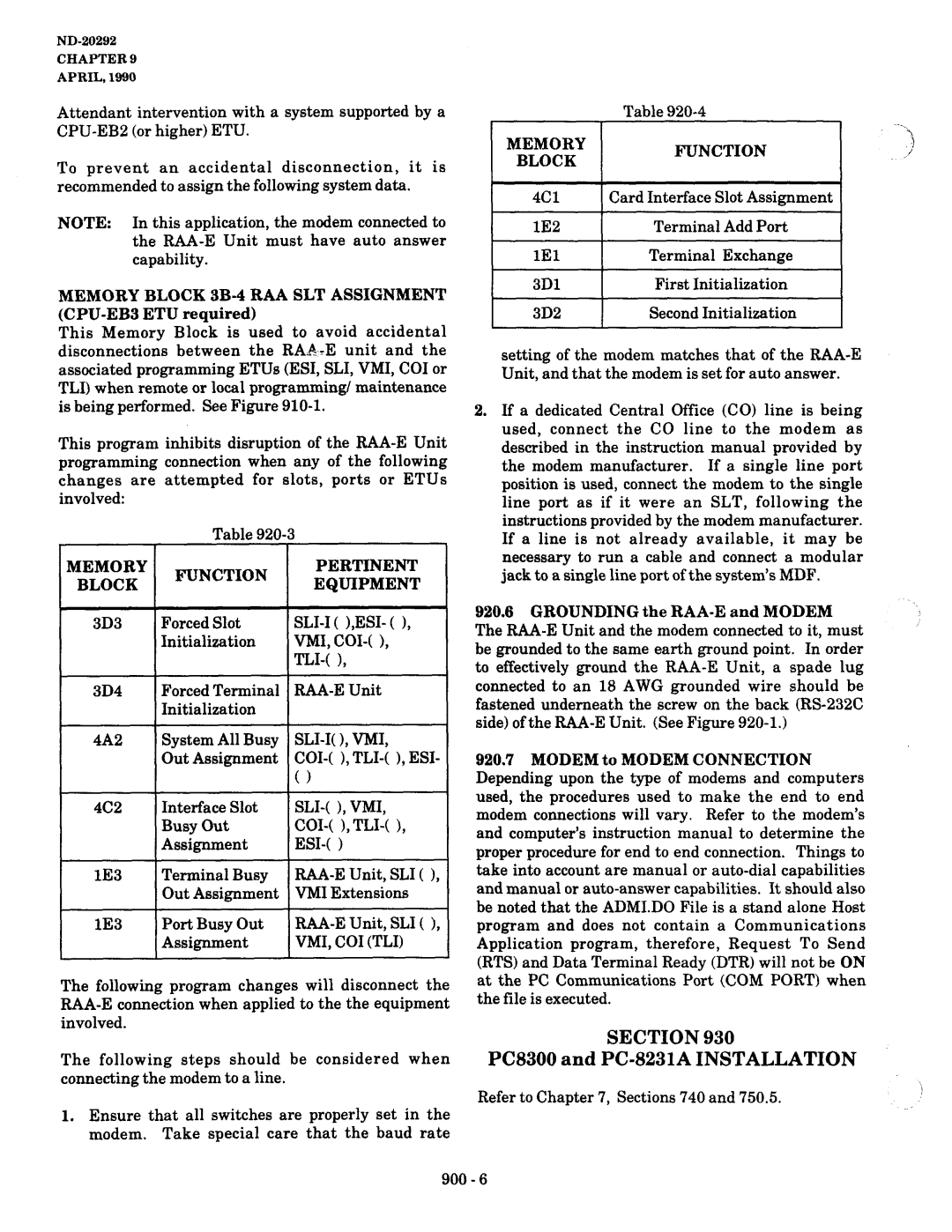
Memory Block 4Cl
Card Interface Slot Assignment
General Information Card Interface Slot Assignment
2A1,4C2
Etiu
Memory Block 4C2 Interface Slot Busy OUT Assignment
U L E
Interface Busy Module
Interface Slot Busy OUT Assignment
Enters new module and slot number
Dial Tone INE TYPETRK.GZ Delay
Select
TYP Trunk GROUP?
Type TRK
General Information TLI Line Type Assignment
2AlO,ZBlO
2Cl-2C3,2C6
2E1,3C2,4Cl
Memory Block 4E2 TLI Dial Tone Assignment
Dial
ASS Trunk GROUP?
TRK-G2
General Information TLI Dial Tone Assignment
QFJ
Memory Block 4E3 TLI Digit ADD /DELETE Code Assignment
TLI Programming
ADD
Code Trunk GROUP?
General Information TLI Digit ADD / Delete Code Assignment
14E1.4E2 12A10,2BlO
Block 4E4 TLI I Initialized Values
TLI
ALI ZEI Trunk
TLl
Defaults
4E4
General Information TLI I Initialize Values
4El-4E3 2A10,2BlO 2Cl-2C3,2C6 2E1,4E5-4ElO
F Line Program Mode TLI ALI
Memory Block 4E5 TLI II Initialized Values
TLl INITIALIZE2
TRUNKGROUP1
Feature PR-OGRAMMING
TLI II Initialize Values
Guide to
Memory Block 4E6 TLI Initialized Values
INITIALIZE3 Trunk GROUP4 I I NI TI ALI ZE3 TRUNKGROUP?
Example Trunk Group
4E6
General Information TLI Ill Initialize Values
Memory Block 4E7 TLI-IV Initialized Values
Programmi
ALI ZE4
SLOT? ALI ZE4
4E7
Initialized Values
LINEsurroNS-l- Function
Uoo 0010 00113 100
Line Program Mode Programmi
Memory Block 4E8 TLI-V Initialized Values
ZE5
ALI ZE5
4E8
General Information TLI V Initialized Values
4El-4E7 2A10,ZBlO ‘ZCl-2C3,2C6 2E1,4E9,4ElO
Function
Port to Hunt Group
Tandem Port Asgn
EXT300
Hunt Tandem Port Asgn
4E9
General Information -TANDEM Port to Hunt Group Assignment
LE2,4Cl 2A10,2BlO 4El-4E8 2Cl-2C3,2C6 2E1,4ElO
Line Program Mode Programmi Tandem Hunt Asgn
Tandem Hunt Asgn
Hunt Tandem Port Asgn TRK
4ElO
II General Information -TRUNK Group to Tandem Hunt Group
Memory Block 5A Station
RI NG DAY
Copy
START???
Guide TOI Feature Programming
General Information Station Copy Assignment
Memory Block 5Bl- CPU Initial
History
14JAN22-88
CPU Initial Clear Data
General Information CPU Initial History
CPU Initial
31JAN04-88
ROM
SYS Prog Check Error
Memory Block 5B2 System Program Check
OFF-LINE Program
SYS Prog Check
General Information System PR0GRA.M Check
Program no
ROM 00 ROM 02,03,04,05,06 ROM 06,07,08
ROM 128~
Memory Block 5B3 Interface Slot Check
OFF-LINEX.Xx
MOD SLOT5
Xxx
5B3
General Information Interface Slot Check
Error Count
Terminal Check DSS? Error Count
Memory Block 5B4 Terminal Check
Terminal Check
5B4
General Information Terminal Check
Memory Block 5B5 SOFTWARE/HARDWARE Slot Status
Status
MODULE? Slot
MODULE1 SLOT?
General Information SOFTWARE/HARDWARE Slot Status
KEY Function
Spkr
TLI
OFF Line Program Mode MAINTENANCE1 T E RM Status TEL???
Memory Block 5B6 SOFTWARE/HARDWARE Terminal
Xxx Hyyy
S3,CH2 Xxx Hyyy
586
General Information SOFTWARE/HARDWARE Terminal Status
1E2
Decrements terminal number
OFF-LINE Program Mode
MAINTENANCE2
Memory Block 5Cl- System Data Last Change
SYS Data
System Data Last Change
OI3I 11121JIAINj2121 LlAI-1014j
Memory Block 5C2 Data Dump
000000
400000
Address
General Information Data Dump
Addressdata
Xxyy
This page Intentionally Left Blank
Section Function Timer Chart
Function Timer Chart Contd
Timing Value
Timing Value Timer
350
Contd
300-260
Section CODE/CALL Restriction
3E8
3E9
OCC Other Common Carrier Code Parameter
Digit Disconnect station
Step Second digit dialed
Table is allow
Any Digit Allow User To dial Another digit Next
Step 5th Digit
Digit Allow
New Found Table found
Is allow Allow user Free dialing System
Allow user Free dialing Is deny
Station System Deny Disconnect 300-265
300-266
1+ Dial Area
E2, Ll-L8 on
Direct Dial Area MB 3E2, Ll-L8 OFF
Other Common Carrier Access
Special Code Override Table
MB 3E1, Puerto Rico Type Dialing
Jobspecificationsheets Tableofcontents
JOB Specification Sheets Table of Contents
JOB Specification Sheets
JOB SJ?lWlFlCATION Instructions
For
Extension Assignment
Entry
IL3
Assignments
JOB Specification Instructions for
Attendant Associated
Being Assigned Extension Number Assignment of DSS Buttons
Blocks lC-1, -3
DSS Button Assignments
For EDE-30
300-277
Memory Block lC-2 BLF Feature to Telephone Assignment
ETE-16D- Multiline Terminal With BLF Feature
Description Entry
Extension Number Each
Block lC-2 BLF Feature to Telephone Assignment
Memory
Module
For Memory Blocks lC-5, -6, -7
Itemdescription
UJ5 iSYJ!iLlF‘lLA’l’lUN 1N S’l’K. U C‘l’lUN
Extension Number XXX or
300
Itemdescription
Entry
300-283
JOB Specification Instructions for Memory Block
Data Service
LD-2
Block lD-2 Data Service Assignment
UP to 16 Digits / CHARACTERS, #, *, l- 9, Pause
Iin
L8Z-OOC
Description Assigning Third Programming
Allow Prime Line Pickup in the System
Separate Single Digits O-9 EKW
Circuit Number From the CO
Trunk Tenant
Dial When Using a TIE Line Station Being Assigned
Maximum Number of Digits That a Station can
300-291
JOB Specification Instructions for
Memory Blocks
Memory Block 2BlO is located on
VMI extension number
Memory Blocks 2B-3, -4, -7, -8 and 2C-5 DIT/ANA
Assignments
Modem Pool and SLT to VMI
2RR
Specification Instructions For Memory Blocks 2C-7
Relay Assignments
JOB
\/FOR TIwNI&R~~P
NG Control
For Assignment
1NOTE 48 Virtual Extensions Are Available
Memory Block 2C-10 Virtual
Extension
300-298
Timing Required For Each FE URE
Memory Blocks 2D-1, -2 & -3 SYSl fi,M Time Base Assignments
SEC
2D-3
SEC
‘NEW Feature
ANY Unused Code Pattern
Memory Block 2E-1 System Access Codes
None
Inone
1NONE
NEW Feature ANY Unused Access Code Desired
Speed
Memory Blocks 3A-2, -3, -4, and 3C-1
Memory Blocks 3A-2, -3, -4, and 3C-1
Specification
For Memory
3B-1 6, -7
Centrex Ringing Station Hunting
3B-5
3B-7
3B-8
When Puerto
Type of Dialing Available in the Area
Dialing Methods Used for Toll Calling
Rejection of First Digit Dialed
3E 1, -2, -3, -4,
Blocks
System Rest
Memory Block
3E5
3E6
3E7
Description
3E5
Dtmf or DP
Timing of CO / PBX Hook Flash from
Memory Blocks 4B-1 and -2 CO1 Initialized
JOB Specification
Hook Flash Start Time
L-3
YES or no
SLI
CO1 Group
VMI Initialize
ESI-EB Data and Second Voice Path Assignment Memory Block
TLI-EB
CNF-E
Memory Block
4C-1 Card Interface Slot Assignment
Module Number
M--w
Description Entry
300
Description
Memory Blocks 4E-4, -5, and -6 TLI Initialized Values
40 ms. 180 ms 60 ms. 760 ms
TLI Initialized Values
Descriptionentry
Page
Chapter Station Operation
Chapter Station Operation
Consultation Hold Broker’s Call
General
1 idol I ILlI Iniei I I
Sample LCD Indications
1 IElXh’l ILlI INlEl 1 1
I I I I I I I I I I IS1210 1101 I4151 Io~cITI lslsl 1~1~11
1i’
Ifiri
Sample LED Indications
IDI1 ITI IClAlLlLl 1 1 1
I I I I I I I I I I I I I ’
I I I I I I I I I I I I
101~1~112181
I I I I I I I I I I I I
I I I I I I I I I I I I I 1101I4161 IoIcITI lzlsl Ifiri
1101 I5121 101~1~1 12181 Ifiri
I lclol I IL II Iwei I I
I Idol I ILlI WI I I
Prime Line
Land 1x1
Tie Lines & did
ITI Iiei ILI Iinie
IoIcITI 121.81 Ifirii
Page
01-l
Sample LED Indications Sample LCD Indications
Iliw
LIKIW~I
L I lslTlElVlEl 111317 1101
Handsfree Call
1101 I4151 101~1~1 12181 Ifirii
1101 I4151 101~1~1 lzlsl 1~1~11
101~1~1 12181 1~1~11
Ilo1 I4151 101~1~112181IFIRII
Eiliaip
1101
1101I
I I I I I I I I
I I I I I I I I I I
LIA P S ElDt 1 I 10151lo 2 I 01 4 5 ~OC~T 12181 Ifir
IJ-ZUBYZ
Ifiri I I I I I I
Ifirii I I I I I I
Ifirii
Sample LED Indications
I I I I I I I I I I I I
IO C
IOC
I IEIxITI 1~11IWI I I I 1101I4151 101~1~1lzlsl Ifirii
~c~o~N~F~E~R~E~N~c~EI I
I I I I I I I I I I I I I llol I4151 101~1~112181 1~1~11
I I I I I I I I I
FRI
John
Depress Hold key and hang up
Icnf LED flashes ANS LED lights
Ilo1 I4151 IoIcITI InIsI 1~1~11
I I I
Sample LED Indications Sample LCD Indications
IOlClTl
161
Pl LED’s gooff 400 ‘/ ’
IOlCtTl
Iext green LED lights IEIxITI 1101 I4151
Lf03l IFlRi
1101 I4151 IOlClTl 12181 k’lRl1 400
1101 I4151 101~1~1 Is181 1~1~1I
1 1 lJlIblMlYl l t
I IEIxITI 1~11 INlEI I I
1 1 1 1 1 1 1 i 1 1 Li’ol I4151 101~1~1 12181 1~1~11
1 1 IJIItilMlYI I I
1101I4151 IoIcITI 12181 1~1~1I
1101 I4151 IoIcITI 12181 Ifir
I2181
Ifirii
Lslsl
1101 I4151 101~1~1 12181 1~1~11
Sample LCD Indications
1 t lSlTlElVlEl 1 1 1101 I4151 101~1~1 lzlsl 1~1~11 400
I4151
1101
I I I I I I I I I I I I
Ifiri
CNF
Ipiairiki Inib RI I? I I
Isie
Ifir
ElEXT green LED lights
I I IsITIEIvIEI I I 111317 llol I4151 IOlClTl Isisi IFlRlI
Green LED lights
1101 I4151 ~oIcITI 12181 1~1~11
Ifiri
1101 I4151 101~1~1 Msl Ifirii 400
CO/PBX
BhJISIfl 1 1 1 1 1 1 1 1 111317’
1101 I4151 IoIcITI Mel Ifirii
I I I I I I I I I I 1101 I4151 IoIcITI Mel Ifirii
I I I I I I I I I I
1101I4151 lolcl~l 12181 1~1~11
101~1~112181
I I I
Jioi
ITI
I I I I
Iciailil
~oIcITI
Ilol
IoIcITI
IoIcITI Ifirii
BlUlSlYl 1 1 1 1 1 1 1 1
I I I I I I I I I I I
1 1
Iext 1EXT
1 IElXtTl ILlI IN/El 1 1
BbJlSlYl 1 1 1 1 1 1 1 1
CO/PBX green LED is lit steady
ElLlAlPlSlElDl I lOlOl 1101 l415l
Lslsl ~1~11
Aicicioiuiniti IcIoIDIEI I?1
Ilii
INlEl
LClOlDlEl
12181 ~1~1 Lll2l3l4lSl6 Ilo1
1 IClOl 1 ILlI INhI 1 1
Irieipieiaiti
111111111111111
Depress line key programmed for Do Not Red LED lights steady
~11 INlEl
Isieit
Llol I4151 IoIcITI 12181 1~1~1
1101 I4151 IoIcITI lzlsl 1~1~11
Fiwidi IAILILI. I 1~101~1 Isieit
FlWlDl IAlLlLl 1113171+ 1101 I4151 IoIcITI 12181 1~1~11
I I I I I
1101 IoIcITI 12181
1101 I4151 101~1~1 lslsl 1~1~11
II417
1113171+
1101 L4151
1101 I4151 IOlClTl 12161 IFlRlI 400-65
ElCNF LED flutters Icnf LED goes off 400
ISPlDj
SPD RIK
IAlC
Sipidi I I Itiriki Mcbl I
IAlCl91
I I I I I I I I I I I I I 110’1 I4151 101~1~1 l2l8l Ifirii
SkIDI I 1 lTlRlKl IAlCbi I
111
111111111111111
Itiriki
Aici
IFI
1101 l45l
IoIcITI Lslsl
Sample LCD Indications I I I I I I I I I I I I
IFI
Itiriki
PiRIOIGIRIAIMl ISlPlDl l?l?l
1 IElXlTI ILlI Inpi I 1
1101 I4151 101~1~1 lzlsl 1~1~1I
IMIuIsIIIcI Inibiri I?I I
JlL‘
Depress the DSS key programmed for calculator function
SlPlDl
IAIcI
1101 l4151 lOlClTl 12181 lFlRl1
LCD during
Calculation, do not continue making entries
Addition
Input 123
‘ND-20292
ND-20282
I IEIxITI 1~11ppl 1 l 1 1101 14151 IoIcITI 12181 1~1~1
Iiiiiiiiiii
Ill
Ioiciti
I I I I I I
Ifir NE’W
LlK11161 lVl lMlAlIlLl l
Imiaiiili
IV! Imiai
4151
OCT
ZUZYa
ITIoI
Diaitiai IP Iaitihi
Isitieiviei
Viei
FIR11
Steve
OCT FRI Steve
Not Ready
CAL
Inigi
Inigi Datja
Ilii Iniei
TIO
Fjrii
IsITIEIvIEI
Diaitiai
Diaitiai Ipiaitihi
CIT
T ElV El 1 1 3
Ill3
IsITIEIvIEI
MM’YI NOT’READY
Mmyi Data
M red LEDs flash IDR red LED flashes IDR green LED lights
TEXT-lLED goes off
~A~T~A
IPI!$HI
I I Isl I Ivl I I I I1
I I IsITIEIvIEI I I I1
Data END
Steve Data END
I I IsITIEIvIEI I I I1 1317. ilo 14151 Io~c~T\ lep3l 1~1~11
I I IsITIEIvIEI
~A~TA~ Ipiaitihi
OCT FRI Data Path to END
400-96
Steve
OCT
Data Steve
END
EIV
CIT
OCT FRI Steve Data Path Busy VIE
Octi FRI
IsITIEIvIEI
1101 14151 olc TI 12 81 1~1~11
EVE
Data Ressrve
Ifir
Sample LCD Indications Xiti Inie
AIL Wiaii Inig
AIT
WA1 Tiiing
Lw4DlYl Ill311
I I I I
I I
DIA T a
Sample LCD Indications EIX
OCT FRI RIE Rieserved
MODEM/2
I I I I I I I I I I Ill410
I I I I I I I I I 1
I I I I I I I I I I I I
1ANS
Sample LCD Indications DIA
OIN
EIM2
I I I I I I I I I I
I I I I I I I I I
I I-I I I I’I II I‘I~I
DepressDTkey
Red LED lights IDT redLEDgoesoff
DblTlAl iElNlDl I t 1 I 1113tl
1101 14151 Ioc~T~ 12181 1~1~11
Ii I I I I I I I I I I I I
Datia
Sample LCD Indications DIA TIA Onto M/ODEM,2
Bold
Llol 14151 ~oIc~TI 1218 1~1~11
I lclol I I,LI Iinie I I
I I I I I I I I I I
I I I I I I I I I I
RIESERVEDMODEM2 Data Error
OCT FRI Elapsed
FRI OCT Elapsed
Busy Elapsed OCT FRI
400-112
Green LED on the CO Add-On Module lights
1161 I4151 IoIcITI 12181 Ifiri 1511
LOjOl I317
Eiliaipisieidi
LOClTl
Iliiiniei
Eiliaip
1 ICI01 1 ILlI INId 1 1 1 1101 I4151 IoIcITI 12181 Ifiri
IoIcITI
I2181
1101 I4151 IoIcITI 12181 Ifirii
Ioct
Not S T AIL/L
Firi
I I I I I I I I I I I
DepressPrimary extensionline key
Lift handsetor depressSPKR key to receive dial tone
OCT Busy OUT
I I I I I I I1
IoIcITI 12181 1~1~11
See Sections 420.1.2,420.1.3 and 420.1.4 of this manual
IoIcITI Lalsl
I I I
I I I I I I I I
DSS red LED lights
11~1~1IzIoINIEI I II IPIAIGIE- 1101I4151 101~1~1I2181 1~1~11
III Ipiaigie
Lift handset Idss red LED lights
Depress DSS key on the DSS/BLF
Message Waiting ToSet
INI1 IGlHb’l IMlOlDlEl ISlEIT
~EIxITI
Iliiiniei
1101 I4151 IoIcITI 12181 Ifir
1101 I4151 101~1~112181IFIRI
INT red LED goes off Primary
Red LED is lit steady Red LED goes off
I 1~11 Igihiti I I I
1101I4151 101~1~1lslsl Ifirii
Iiii
Iciodei ICI
Ifir I I
Ifir
IEIxITI ~L~INIEI 1 1
FlWlDI IAlLlLl 1113171+
IEIxITI l~l~l~l~l I I Llol I4151 IoIcITI 12181 1~1~11
1101 I4151 IoIcITI
FlWlDl lAbILl 111317ld 1101 I4151 lolcl~l 12181 1~1~11
Depress primary extension line key Lift handset
I IEIxITI
SIPIDI
IAIcI ?I
LSlYlSlSlPlDl
SYSSPD??
CNF LED goes off CNF LED flutters
Il‘ol I4151 IoIcITI lzlsl 1~1~11 PIR OlGjRAlM lSPlD ?I?
PIR Oigiriaim SlYlS Sipid ? ?
Sipidi 1415 I Itiriki I~Ic1713 ~1~67~5~3~7~0~0~0~ 1 1 1 1
ID AYI
ID a YI
DEC set by line key
Llol I4151 lOlClTl 12181 IFlRlI 400-136
ND-20292 IHAPTER 4 April
Sample LED
Icnf LED
Icnf
Nioi
I I I I I I I
LOl 14151 lOlClTl j281 lFRlI
Pirio
IAIcIcI~o~u~NIT
Day Mode
Night Mode
LED flutters PIRIOIGIRIAjMj LSPlDl ? I?
Depressdesiredline key Green LEDs light
400-142
Consecutive dialing cannot be made in the following cases
Abandoning a Call a Restore handset
Step Calling
Station Hunt Originating
Placing a Call on Hold
Procedure 400
To cancel a Trunk Queue
Receiving Trunk Queue Recall
Original call
‘-r
Calls can be transferred
ZzJz
Internal Zone Paging To Originate
To Answer Meet-Me
External Zone Paging To Originate
Alternates
Can be Routed Another
Chapter
Chapter
Camp-On To Originate
To Answer
Code
Automatic Callback To Set
Maximum number of digits for the account code is determined
To Cancel Lift Handset
ToSet To Set Lift
All call Busy/No Answer
Station’s
Signals cannot be programmed into SLT
Station lockout. ’ 400
Some voice mail systems cannot originate calls
Directory Terminal Operation General
Sample LED Indications Sample LCD Indications
I I I I I I I I I I I I
I I
Icnf LED
ND-20292 DHAPTER April
Number of Depressions Digit
I I I I
400-169
As 1 digit
Sample LED Indications
400-172
I Ifiwdi IAlLlLl
Sample LED
Maintenance
Chapter Maintenance
Tolerance Measuring
CPU-E
TP2
TP3
Section Troubleshooting Flow Charts
Section Self Diagnostics Maintenance
Chapter
Flow Chart Number
500-6 500-7 500-8
Index Table Condition System Down
Partial Operations
500-6
500
MMC
Radio Frequency Interference RFI
Test system using default program
Affected Muitiline
AlITerminalseerminals
Call Dropping
MFR-EA
MMC-E
Multiline Terminal Function Problems
500
Multiline Terminal Dial Tone Access Problems
No Dial Tone Access on SLT
Ringing Problem on SLT
500
Low Volume Problems
External Paging Problem
Smdr Output Problems No Call Accounting System
Chapter Etis
Electra MARK11
Plantronics JS-180 Jackset Connection
Page
ET1 Number
ADA-E Unit installation
4of
Sw*il
Panasonic Autodialer Connection
2of6
3of6
4of6
5of6
Autodialer
Genesis Genie Voice Mail System Connection Procedure
MDF
DTE
Electra MARK11 Dswblf CO ADD-ON Module Upgrade
2of4
3of4
EII
Dasa D-4800 Directory Dialer Connection
Knsure the correct access ptnc!l is
3of
DUnplug Llna Co14
Dipswitch
ADA-E Installation
Nformation
2of8
ET1 Number MK-006 Date February
4of8
Soft3
Diskcapacitor Plastic SLEEVE4 Handset Connector
7of
8of
Handset Amplifier Connection Procedure
Page
ET1 Number MK-007 Date March
Rsr
ADA-E Unit Installation
HAYES@ 1200 Smart Modem Connection to
Procedure
Access Panel Removal
I m
ETE-GD-1
NFORMATlOt
Electra MARK11
Other Requirements
3of6
Test Procedure
Power Supply
12 on Unit
5of6
Front View of W-34X and Pin Xumbers
Nformation
Programming
Electra MARK11 System
4of
Side
Forma T/On
2of6
ET1 Number MK-011
ETE-10K-1
DIP Switch SW2
ADA-EInstallation
AEC TWO Channel Announcement Machine
2of6
Switch Setting SW1
Testing
Attendant Activation and Deactivation of Delay Announcement
‘...~
AEC TWO Channel Announcement Machin E
ETI Number MK-012A
ETI Number MK-012A
Attendant Activation and Deactivation of Delay Announcement
ETI Number MK-01 2A
Testing
ETI Number MK-012A
System Frame Iground Connector ECR-E ETU Male
Cable DIP Switch Levers Shown Black
Announcer
Conductor
Internal Jumper Plug Settings 7OF7
Page
NECAmerica Inc. Switchinq Terminals Division
Procedures
Electra MARK11
ETI Number MK-014 Date April Description
Test Procedures
ETI Number MK-014
Ground Starttrunk
SLT SLI-EB OUT Fggnd
TIN Tout RIN Rout
TIN Tout RIN Rout GND
Viking Door Phone
ETI Number MK-015 Date April Description
ETI Number MK-015
Or W-2000
TOP
Figure Handsfree Doorbox connected to COI-E/EB ETU 4OF6
5OF6
Figure Door Release connected to VMI Port
NECAmerica Inc. Switchins Terminals Division
SET UP Procedure
ETI Number MK-016 Date April Description
Parts Required
Procedure
ETI Number EMK-016
RAC-E Unit
Inserting the Eprom and Adding the a Revision Label
Adding Revision Label 2A to Outside of RAA-E Unit 4OF4
Pathfinder PHONE/DATA/FAX Switch
Description ETI Number MK-017 Date April
ETI Number MK-017
References
Site Requirements
ETI Number MK-017
Connecting theviking FaxJack 4OF5
To Telco
To TE LCO
NECAmerica Inc. Switchin Terminals Division
ETI Number MK-018 Date April Description
Parts Required SMDR-E ETU
ETI Number MK-018
SMDR-E ETU
Configuration
DESCRIPTION%
ETI Number MK-019
ETI Number MK-019
Repartee Connection Block Diagram 4OF4
MDF
Dterm II Single Line Telephones
ET1 Bulletins
ET1 Number Description Date
Dterm
ETI Number DS-001 Date April Description
Limitations
1OFS
ETI Number DS-001
Efl Number DS-001
White
TX1
TX2
ETI Number OS-001
ETI Number DS-001
Sofs
Connection of Northern Telecom
ETI Number DS-002
IIC3
Companion 2 Cables
IC3
ETI Number OS-002
Speakerphone Cable Exit Groove on Dterm II Telephone 5OF5
ETI Number DS-003 Date April
None Parts Required
ETI Number
ETI Number DS-003
RX1
RX2
QBI
ETI Number OS-003
ETI Number DS-003
Lackret JS-180 Cable Exit Groove on Dterm II Telephone 5OF5
ETI Number DS-004 Date April Description
Connectors
ETI Number DS-004
\ &I
ETI Number W-004
Page
II& l-l
ETI Number OS-004
TA-20 or S-l 1 Cable Exit Groove on Dterm II Telephone 6OF6
Connection of Audio Tape Recorder
ETI Number DS-005 Date April Description
Procedure
ETI Number OS-005
Step
Stepa
ETI Number DS-005
PCB Connection for Automatic Operation of Tape Recorder 4OF5
Cable Exit Groove
ETI Number OS-006 Date April Description
ETI Number OS-006
Connection of a Panasonic Autodialer
ETI Number DS-007 Date April Description
ETI Number DS-007
Upward Downward
Connector TX2 CONNECTOR6
Cia
ETI Number OS-007
Dtem
Series
II Telephones
ET1
Switchina Terminals Division
Plantronics is-1 80 Jacket Connection
NEC America, Inc
ET1 Number DT-001 Date December
2of
Access Panel Removal
ADA-E Unit Installation 4of
ET1 Number DT-001 Date December
DIP Switch SW2 Setting for JS-180
ADA-E Unit
NSA-171694
To Plantronics Jackset Model
NEC America, Inc Switching Terminals Division
Parts Required
ET1 Number DT-002 Date December
2of6
ET1 Number DT-002 Date December Operation
ET1 Number DT-002 Date December
4of
ET1 Number DT-002
ADA-E Unit Installation
DIP Switch SW2 Setting for Autodialer
NSA-174694
Dterm Series
ET1 Number DT-03 Date December
ET1 Number DT-003 Date December
Access Panel Remova\
Date December 19%
Tone Commander TA-20 Amplifier
ADA-E Unit
NSA-171694
ADA-E Unit
NEC America, Inc Switching Terminals Division
DtermSERIES
Dterm Series II Terminals
Telephone
Procedure
ET1 Number DT-994 Date January
Testing
ET1 Number DT-004 Date January
Access Panel Removal
4of6
DIP SW1TC.H SW2 Settings
5of6
ET1 Number DT-004 Date January
TO-W Ir3To Remo
ADA-E Installation
6of6
Northern Telecom Companion Speakerphone Connection
Reference
ETI Number DT-005
ETI Number DT-005
Access Panel Removal 4of
ADA-E Unit DIP Switch SW2 Settings
Companion
ADA-E Installation
EMK-3050.001
ADA-E Unit Stock # Phonebeam Speakerphone with IR2 adaptor
ETI Number DT-006
ETI Number DT-006
Line Cord Apply Pressure
ADA-E Unit DIP Switch SW2
SElTlNGS
ETI Number DT-006 Cable Exit Groove ETE-CD
ADA-E Installation 7of7
ADA-ER Unit
From one end of the two conductor wire Step
Testing
Access Panel Removal 4of7
ADA-ER Unit DIP Switch SWZ Settings
Lo 0 l .J
ADA-ER Installation
ADA-ER Installation
ET1 Number MK-011
4of
Settings
ETE-GD-1, ETE-16D-1, ETE-16K
Limitations
Automation Electronics Corporation
NEC America. Inc Teiminals Division
Date December
Procedure
References Operation
ET1 Number MK-012 Date December
Switch Setting SW1
Terminal Station Cable
OFF
SW4
Testing
Attendant Activation and Deactivation of Delay Announcement
ET1 Number MK-012 Date December
ECR-E ETU
JK3 c
JK2
AEC Dual Line Announcer Model 212 Plus
ETI Number MK-012A
Revised from MK-012
Automation Electronics Corporation
Terminal Cable
Switch Setting SW1
SW2 OFF SW3 SW4
BGM
Testing
Announcement ClHANDSET
Internal Jumper Plug Settings 7OF7
Page
Dees Automatic Ground Start Unit
ETI Number MK-014
TIN OUT RIN Tout
Viking Door Phone Door Release Connections
Page
ETI Number MK-015
ETI Number MK-015
ETI Number MK-015
ETI Number MK-015
RAA-E Unit Upgrade
ETI Number EMK-016
RAC-E Unit
ETI Number EMK-016
Pathfinder PHONE/DATA/FAX Switch Connections
ETI Number MK-017
ETI Number MK-017
To Telco
To Telco Phone Jack Port Machine MODEM/ P.0.S Terminal
AlECAmerica Inc. Switchinq Terminals Division
ETI Number MK-018
SMDR-E ETU Ribbon Cable from Rear of Computer
Active Voice Repartee Voice Mail System Connection Procedure
ETI Number MK-019
ETI Number MK-019
ETI Number MK-019
ET1 Bulletins
Dterm
ETI Number DS-001
Speakerphone Cable Connection
ETI Number OS-001
Line Drawing For Completed installation 5OF5
Connection of Northern Telecom Companion 2 SP
ETI Number DS-002
ETI Number
Insulate
Sofs
Dterm
ETI Number DS-003
+ro
Insulate
ETI Number OS-003
Dterm
ETI Number DS-004
LCl8-l
DS-004
IC3
TA-20 or S-l 1 Cable Exit Groove on Dtetm II Telephone 6OF6
Dterm
ETI Number DS-005
Step
IC4
Chapter Least Cost Routing LCR
Chapter Least Cost Routing LCR
Section Equipment Identification
Chapter
Section Installation of LCR-E ETU
Installation Ofthe LCR-E ETU
Section Installation of PC-8300
Battery Backup
Printer Connection
Programming System Memory For LCR
700-10
Then p
Depress1F2 1,lF?l ,thenlF16I
LCR Program Construction
Chapter
Chapter
Route Advance Tables
Initializing the PC-8300
27 Rear Side View of the PC-8300
IBM LCR
Programming the LCR-E ETU KEY Layout and Explanation of Keys
28 Keyboard Layout Number Keys l-9
Data
Route Advance
Route
Route Modify
TE Table Modify
Other Keys Used P, #, *, INS, DEL
Code 0 8
Input of Data
+z+
At this time, any table to be down loaded can be selected
Program Loading
Areacode ? ml
Modify Display System Control Enter Menu no
WY%54
Selection of up load mode results in the menu display shown
Verify Mode
Office Code Table Verify Start w
Area Code ,,BL
Pzz7
00 00 00 00 00 00 01 01 01 00 00
With the Modify Menu in the display, depress
Route Table MODIFY*** Table no Advance
Route Table Modify
Table Modify DEL ADD ETR Code TBL02
Sample LCD Indications
Office Code Table Modify Table NO. ?
700
Enter Menu NO. c 700
Area Code f,BE Display
Daily Schedule Display Daily Schedule Table NO.?
Display Table NO. ?
Office Code Table Display
Home NPA Code Table Print OUT Start Normal END
System Data Clear
Phase Executing Normal END Abnormal END Line Trouble
Error Messages
FDD I/O
Start \ Station
NNX + No LCR
Normal Operation No LCR 1YES
1st. Priority
ADO
700-64
UzazcI I I I I I I I I I I I I I I I I I I I I I
=I=
‘700
Weekly Schedule Tables Descriptionentry
I I I
Daily Schedule Table
Daily Schedule Tables
700-72
Route Advance Tables
Route Tables
Route Tables
Office Code Tables
Chapter
700-78
SD-20292
Chapter Voice Mail Integration
Chapter
Section Programming
Parameter Minimum Maximum Default Increments Memory Block
This page Intentionally Left Blank
Page
Remote Administration Adaptor
Tzx
910.2 PC-8300 Personal Computer
LlolBLlmElllol
R&J-E Switch Setti*g
Electra Markii
PC8300 and PC-8231A Installation
Text Telcom
General
FRI Hook
#*O
LK Asgn
Pmqpiziq
Pmq /-xmqpixiq
Executing IBM Type Compatible Sofiware
Ryl \
JAN 01 MON
System Up’~PL~VD&lWN Load
System Memory UP Load /DOWN Load
Electra Mark 2 Digital KEY Telephone System
Chapter
Verify
900
Page
Page
Page
Page