Appendix D Slot Property
Transponder Cards
D.5.1.1 Module View Tab
The Module View tab displays a graphic of the transponder that is installed in the slot. The number of critical, major, minor, and warning alarms for the module is displayed under Alarm Status. (Moving the mouse pointer over the graphic also displays the alarm counts.) The module status is displayed under Operational State.
D.5.1.2 Identification Tab
|
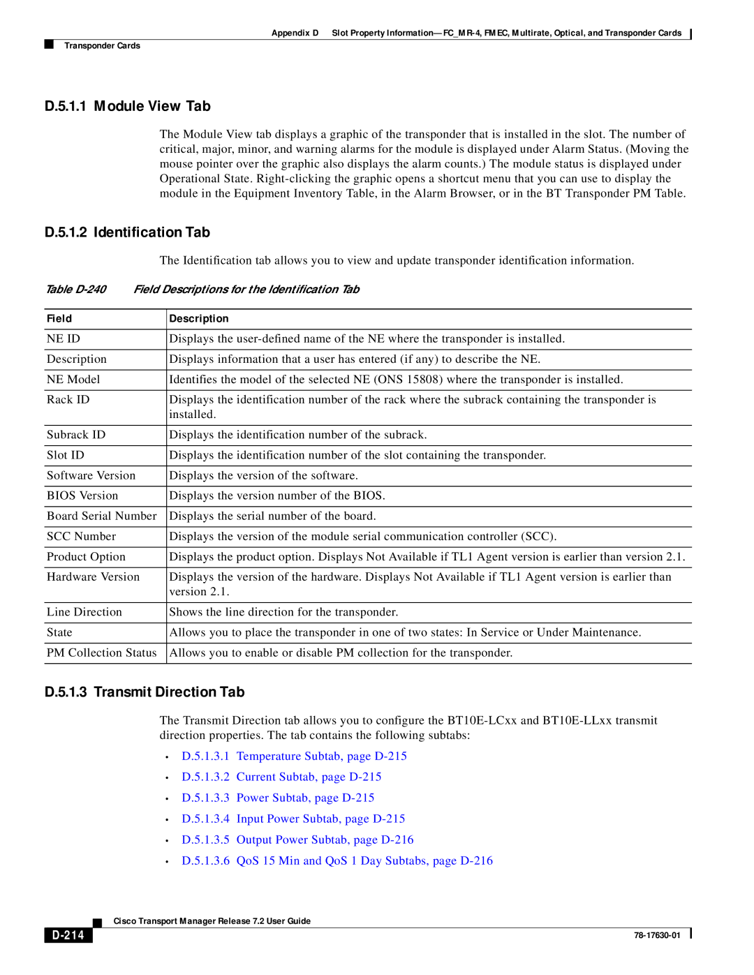
| The Identification tab allows you to view and update transponder identification information. | |
Table | Field Descriptions for the Identification Tab | ||
|
|
|
|
Field |
|
| Description |
|
|
|
|
NE ID |
|
| Displays the |
|
|
|
|
Description |
|
| Displays information that a user has entered (if any) to describe the NE. |
|
|
|
|
NE Model |
|
| Identifies the model of the selected NE (ONS 15808) where the transponder is installed. |
|
|
|
|
Rack ID |
|
| Displays the identification number of the rack where the subrack containing the transponder is |
|
|
| installed. |
|
|
|
|
Subrack ID |
|
| Displays the identification number of the subrack. |
|
|
|
|
Slot ID |
|
| Displays the identification number of the slot containing the transponder. |
|
|
| |
Software Version |
| Displays the version of the software. | |
|
|
|
|
BIOS Version |
|
| Displays the version number of the BIOS. |
|
|
| |
Board Serial Number |
| Displays the serial number of the board. | |
|
|
|
|
SCC Number |
|
| Displays the version of the module serial communication controller (SCC). |
|
|
|
|
Product Option |
|
| Displays the product option. Displays Not Available if TL1 Agent version is earlier than version 2.1. |
|
|
| |
Hardware Version |
| Displays the version of the hardware. Displays Not Available if TL1 Agent version is earlier than | |
|
|
| version 2.1. |
|
|
|
|
Line Direction |
|
| Shows the line direction for the transponder. |
|
|
|
|
State |
|
| Allows you to place the transponder in one of two states: In Service or Under Maintenance. |
|
|
| |
PM Collection Status |
| Allows you to enable or disable PM collection for the transponder. | |
|
|
|
|
D.5.1.3 Transmit Direction Tab
The Transmit Direction tab allows you to configure the
•D.5.1.3.1 Temperature Subtab, page
•D.5.1.3.2 Current Subtab, page
•D.5.1.3.3 Power Subtab, page
•D.5.1.3.4 Input Power Subtab, page
•D.5.1.3.5 Output Power Subtab, page
•D.5.1.3.6 QoS 15 Min and QoS 1 Day Subtabs, page
| Cisco Transport Manager Release 7.2 User Guide |
|
