Appendix D Slot Property
Transponder Cards
D.5.9.5 Input Power Tab
The Input Power tab allows you to assign performance monitoring thresholds for the power entering the receive transponder.
Table
Field
Description
Input Power
Value | When the Update button is clicked, displays the current receive transponder input power. |
|
|
Low | Sets the low threshold for the receive transponder input power in dBm and the alarm severity level. |
|
|
High | Sets the high threshold for the receive transponder input power (in dBm) and the alarm severity level. |
|
|
D.5.9.6 Output Power Tab
The Output Power tab allows you to assign performance monitoring thresholds for the receive transponder output power.
Table
Field
Description
Output Power
Value | When the Update button is clicked, displays the current receive transponder output power. |
|
|
Low | Sets the low threshold for the receive transponder output power (in dBm) and the alarm severity level. |
|
|
High | Sets the high threshold for the receive transponder output power (in dBm) and the alarm severity level. |
|
|
Note See Table
D.5.10 Slot Properties—RXT-10G-N
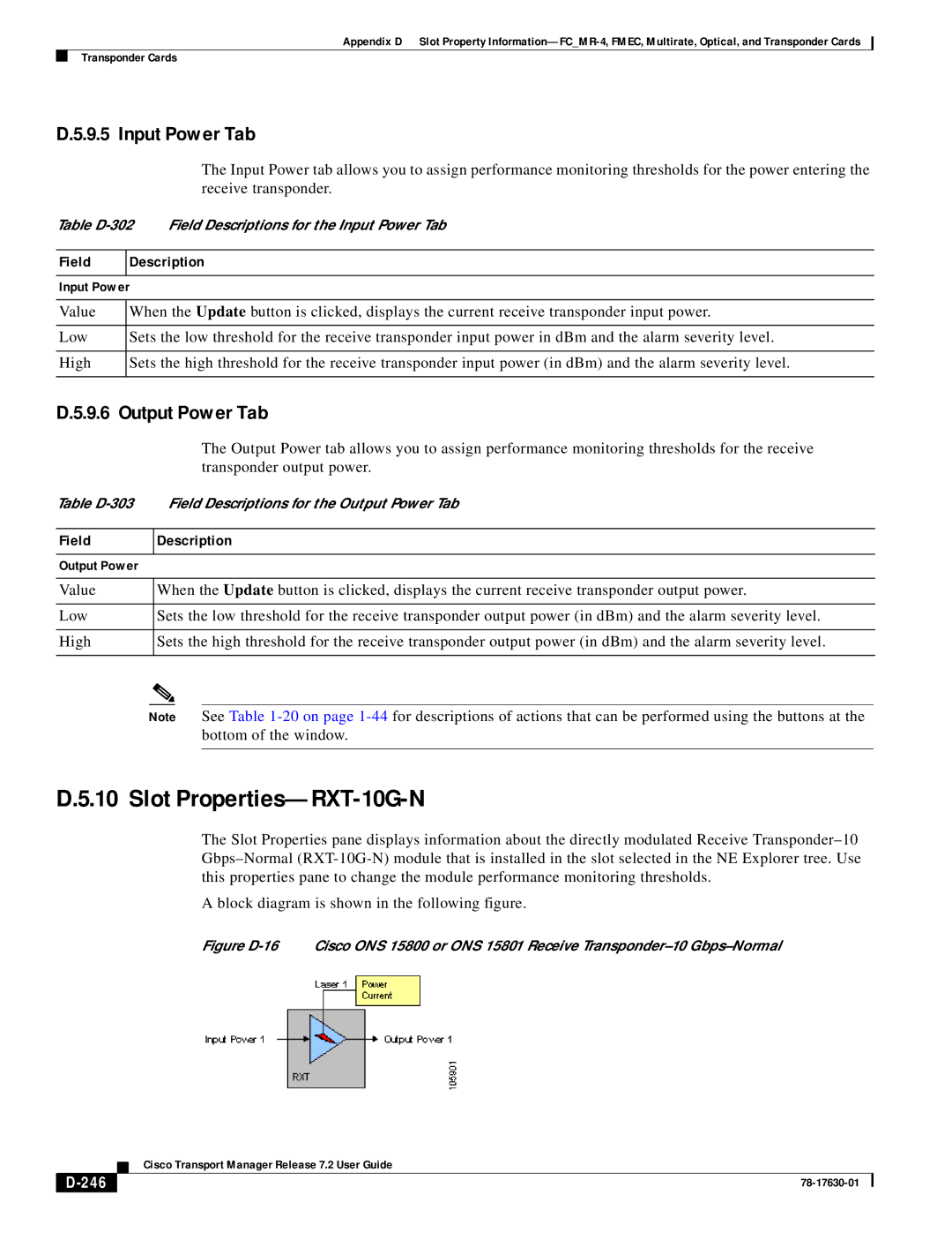
The Slot Properties pane displays information about the directly modulated Receive
A block diagram is shown in the following figure.
Figure D-16 Cisco ONS 15800 or ONS 15801 Receive Transponder–10 Gbps–Normal
| Cisco Transport Manager Release 7.2 User Guide |
|