Appendix D Slot Property
Transponder Cards
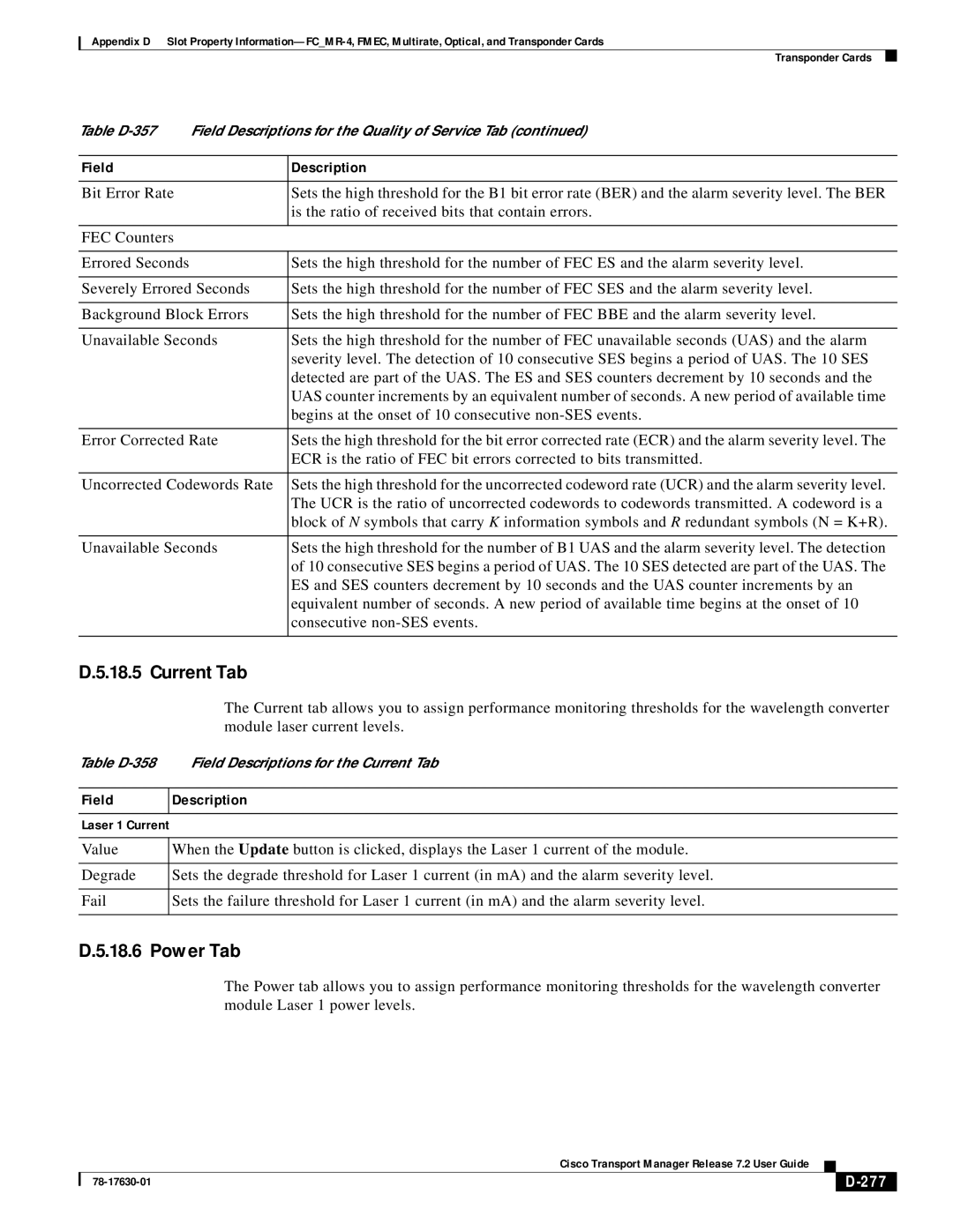
Table | Field Descriptions for the Quality of Service Tab (continued) | |
|
|
|
Field |
| Description |
|
|
|
Bit Error Rate |
| Sets the high threshold for the B1 bit error rate (BER) and the alarm severity level. The BER |
|
| is the ratio of received bits that contain errors. |
|
|
|
FEC Counters |
|
|
|
|
|
Errored Seconds |
| Sets the high threshold for the number of FEC ES and the alarm severity level. |
|
| |
Severely Errored Seconds | Sets the high threshold for the number of FEC SES and the alarm severity level. | |
|
| |
Background Block Errors | Sets the high threshold for the number of FEC BBE and the alarm severity level. | |
|
| |
Unavailable Seconds | Sets the high threshold for the number of FEC unavailable seconds (UAS) and the alarm | |
|
| severity level. The detection of 10 consecutive SES begins a period of UAS. The 10 SES |
|
| detected are part of the UAS. The ES and SES counters decrement by 10 seconds and the |
|
| UAS counter increments by an equivalent number of seconds. A new period of available time |
|
| begins at the onset of 10 consecutive |
|
| |
Error Corrected Rate | Sets the high threshold for the bit error corrected rate (ECR) and the alarm severity level. The | |
|
| ECR is the ratio of FEC bit errors corrected to bits transmitted. |
|
| |
Uncorrected Codewords Rate | Sets the high threshold for the uncorrected codeword rate (UCR) and the alarm severity level. | |
|
| The UCR is the ratio of uncorrected codewords to codewords transmitted. A codeword is a |
|
| block of N symbols that carry K information symbols and R redundant symbols (N = K+R). |
|
| |
Unavailable Seconds | Sets the high threshold for the number of B1 UAS and the alarm severity level. The detection | |
|
| of 10 consecutive SES begins a period of UAS. The 10 SES detected are part of the UAS. The |
|
| ES and SES counters decrement by 10 seconds and the UAS counter increments by an |
|
| equivalent number of seconds. A new period of available time begins at the onset of 10 |
|
| consecutive |
|
|
|
D.5.18.5 Current Tab
The Current tab allows you to assign performance monitoring thresholds for the wavelength converter module laser current levels.
Table
Field
Description
Laser 1 Current
Value | When the Update button is clicked, displays the Laser 1 current of the module. |
|
|
Degrade | Sets the degrade threshold for Laser 1 current (in mA) and the alarm severity level. |
|
|
Fail | Sets the failure threshold for Laser 1 current (in mA) and the alarm severity level. |
|
|
D.5.18.6 Power Tab
The Power tab allows you to assign performance monitoring thresholds for the wavelength converter module Laser 1 power levels.
|
| Cisco Transport Manager Release 7.2 User Guide |
|
|
|
|
|
| |||
|
|
|
|
| |
|
|
|
|
