Appendix D How to Use PLC Function
use byte, word or double word. Furthermore, the two equipments, timer and counter, in PLC not only have coil but also value of counting time and times.
In conclusion, each internal storage unit occupies fixed storage unit. When using these equipments, the corresponding content will be read by bit, byte or word.
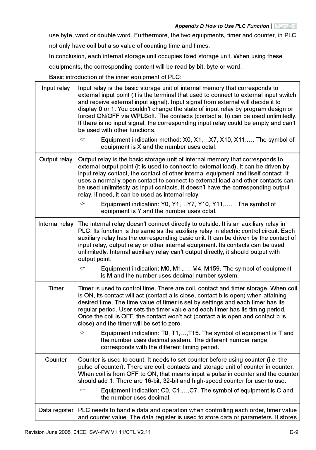
Basic introduction of the inner equipment of PLC:
Input relay
Output relay
Internal relay
Timer
Counter
Data register
Input relay is the basic storage unit of internal memory that corresponds to external input point (it is the terminal that used to connect to external input switch and receive external input signal). Input signal from external will decide it to display 0 or 1. You couldn’t change the state of input relay by program design or forced ON/OFF via WPLSoft. The contacts (contact a, b) can be used unlimitedly. If there is no input signal, the corresponding input relay could be empty and can’t be used with other functions.
Equipment indication method: X0, X1,…X7, X10, X11,…. The symbol of
equipment is X and the number uses octal.
Output relay is the basic storage unit of internal memory that corresponds to external output point (it is used to connect to external load). It can be driven by input relay contact, the contact of other internal equipment and itself contact. It uses a normally open contact to connect to external load and other contacts can be used unlimitedly as input contacts. It doesn’t have the corresponding output relay, if need, it can be used as internal relay.
Equipment indication: Y0, Y1,…Y7, Y10, Y11,…. . The symbol of
equipment is Y and the number uses octal.
The internal relay doesn’t connect directly to outside. It is an auxiliary relay in PLC. Its function is the same as the auxiliary relay in electric control circuit. Each auxiliary relay has the corresponding basic unit. It can be driven by the contact of input relay, output relay or other internal equipment. Its contacts can be used unlimitedly. Internal auxiliary relay can’t output directly, it should output with output point.
Equipment indication: M0, M1,…, M4, M159. The symbol of equipment is M and the number uses decimal number system.
Timer is used to control time. There are coil, contact and timer storage. When coil is ON, its contact will act (contact a is close, contact b is open) when attaining desired time. The time value of timer is set by settings and each timer has its regular period. User sets the timer value and each timer has its timing period. Once the coil is OFF, the contact won’t act (contact a is open and contact b is close) and the timer will be set to zero.
Equipment indication: T0, T1,…,T15. The symbol of equipment is T and the number uses decimal system. The different number range corresponds with the different timing period.
Counter is used to count. It needs to set counter before using counter (i.e. the pulse of counter). There are coil, contacts and storage unit of counter in counter. When coil is from OFF to ON, that means input a pulse in counter and the counter should add 1. There are
Equipment indication: C0, C1,…,C7. The symbol of equipment is C and the number uses decimal.
PLC needs to handle data and operation when controlling each order, timer value and counter value. The data register is used to store data or parameters. It stores
Revision June 2008, 04EE, |
