Setup Guide
Means Power ON. b means Power OFF
Setup Guide
Page
Trademarks
Safety During Operation
Safety Information
Iii
Positions of Labels and Hallmarks for Rwarning and Rcaution
Page
Energy Saver mode
Specifications
Energy Star Program
Recycled Paper
Manuals for This Printer
Manuals for This Printer
How to Read This Manual
Symbols
Vii
Table of Contents
Installing the PostScript Printer Driver
Installing the Rpcs Printer Driver
Installing the Printer Driver Using USB
Installing the Printer Driver Using Ieee
Page
Major Specifications
Features of This Printer
Time Saving
Compact Body
Printer Drivers for This Printer
PCL printer drivers
Rpcs printer driver
Adobe PostScript Printer Drivers and PPD files
Software and Utilities Included on the CD
SmartNetMonitor for Admin
Agfa Monotype Font Manager
SmartNetMonitor for Client
Viewing the Contents of the CD-ROM
Guide to This Printer
Mainframe
Exterior
Power Switch
Front Cover Release Button Power Cord
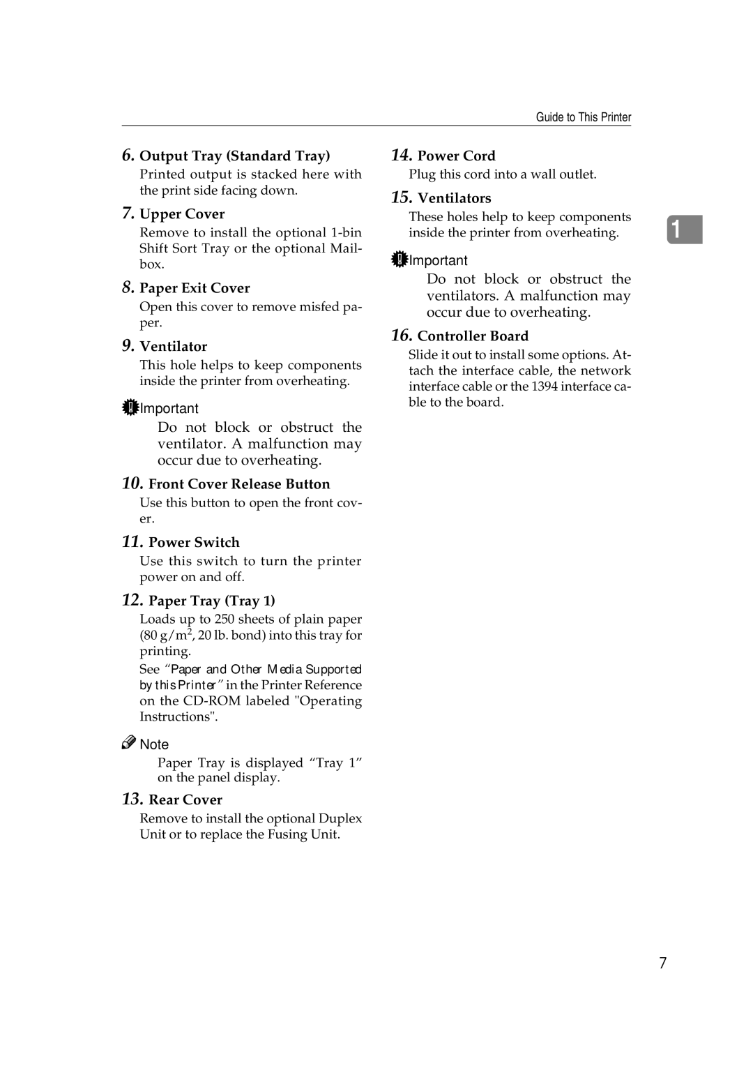
Output Tray Standard Tray
Upper Cover
Interior
Control Panel
Job Reset key
Form Feed key
Menu key
Enter # key
Escape key
Option List
Installing Options
Available Options
Paper Feed Unit Type 2600 Tray 2 or Tray
Envelope Feeder Type
Basic model Printer Interior
Network standard model Printer Interior
Memory Unit TypeB 64MB Hard Disk Drive Type
802.11b Interface Unit Type a Memory Unit TypeB 64MB
Attach the interface cable to the printer
Paper Feed Unit Type
Reference
Envelope Feeder Type
Use a coin to remove the two screws
Memory Unit TypeB 64MB
Pull out the handle of the control- ler board
Pull the handle and slide the con- troller board out
If the Duplex Unit is not at- tached, go to step N
Installing Options
Network Interface Board Type
Installing the Network Interface Board
Fasten the Network Interface Board to the controller board
If the Duplex Unit is not at- tached, go to step O
Turn off the power switch Loop the network interface cable
Connecting the Network Interface Cable to the Network
Interface Unit Type
Installing the 1394 Interface Unit
Attach the 1394 Interface Unit to the controller board
Fasten the 1394 Interface Unit to the controller board
Power supply
Connecting the 1394 Interface
Required cable
Bus
802.11b Interface Unit Type a
Attach the 802.11b Interface Unit
Ing the Configuration
HDD Error Initialize ?
Hard Disk Drive Type
Fasten the Hard Disk Drive
Ready
HDD Initialize Finish OK
Press Enter # to format the Hard Disk Drive
Press On Line
Remove the rear cover in the hor- izontal direction
AD410 Duplex Unit
After installing the last option that
Remove the upper cover of the printer
Bin Shift Sort Tray Type
Slide the upper tray into the 1-bin Shift Sort Tray
CS380 Mailbox
CS380 Mailbox
Installing Options
Setting Name Value
Ethernet Configuration
Network Setup IP Address
Host Interface Network Setup
Network Setup Active Protocol
Menu Host Interface
Network Boot *None
Network Setup Network Boot
Press U or T to display Network Boot
IP Address 192.02k.033.044
Network Setup LAN Type
Network Setup Frame Type NW
Frame Type NW *Auto
LAN Type *Ethernet
Host Interface Ieee 1394 Setup
Ieee 1394 Configuration
Ieee 1394 Setup IP Address1394
Ieee 1394 Setup IP over
Ieee 1394 Setup Scsi print
IP Address1394 192.02k.033.044
Scsi print *Active
Ready
Ieee 802.11b Comm. Mode
Ieee 802.11b Wireless LAN Configuration
Host Interface Ieee 802.11b
Press U or T to display Ieee 802.11b
Address
Ieee 802.11b Channel
Subnet Mask
Gateway Address
Configuring the Printer for the Network
Connection
Installation Method
Select Quick Install
Quick Install
Follow the instructions on the screen
Click Install
Installing the PCL 6/5e Printer Driver
Installing the PCL 6/5e Printer Driver
Select PCL/RPCS Printer Drivers
Setting Up Options
Installing the Rpcs Printer Driver
Installing the Rpcs Printer Driver
Installing the Rpcs Printer Driver
Windows 95/98/Me Installing the PostScript Printer Driver
Installing the PostScript Printer Driver
Installing the printer driver
Click Next Check Local Printer and then click Next
Select PostScript 3 Printer Driver Add Printer Wizard starts
Setting up options
Click the Device Settings tab
Windows NT 4.0 Installing the PostScript Printer Driver
Bidirectional transmission
When connecting with a parallel cable
When connecting with the network
When connecting with Ieee
When connecting with USB
Setting up the PPD file
Macintosh Installing the PostScript 3 Printer Driver
Close the Chooser dialog box
Click Configure
Windows 98/Me Installing the Printer Driver Using USB
Installing the Printer Driver Using USB
Check Specify a location, and then click Browse
Click Finish
Click Change in USB Printer Selection
Macintosh-Creating a Desktop Printer icon
Click Create
Enter the printer name, and then click Save
Printing with Scsi Print
Installing the Printer Driver Using Ieee
Click Open Click OK
Click Browse
Windows XP
Inactivating the Device
Printing with IP over
Found New Hardware Wizard dialog box, and then click Next
Select SmartNetMonitor for Client/Admin
Installing the SmartNetMonitor for Client/Admin
Select Agfa Monotype Font Manager
Installing the Agfa Monotype Font Manager
Using Adobe PageMaker Version 6.0 or
Index
Rpcs
UE USA G074
Means Power ON. b means Power OFF
UE USA G074-8637
Printer Reference
Page
Trademarks
Printer Reference this manual
Setup Guide
How to Read This Manual
Table of Contents
Maintenance Menu 114
Error & Status Messages on the Control Panel
Sample Print
Locked Print
Specifications 157
Replacing Parts 143
Consumables 164 Information about Installed Software 165
System Menu 124
Windows 95/98/Me Accessing the Printer Properties
PCL 6/5e Accessing the Printer Properties
Changing the default printer settings
Making printer settings from an application
Changing the default printer settings Printer Properties
Windows 2000/Windows XP Accessing the Printer Properties
Click Print to start printing
Select the printer you want to use in the Select Printer box
On the File menu, click Document Defaults
Windows NT 4.0 Accessing the Printer Properties
Click OK to start printing
Rpcs Accessing the Printer Properties
On the File menu, click Printing Preferences
Select the printer you want to use in the Select Printer box
Windows NT 4.0 Accessing the Printer Properties
Making printer settings from an application
Make any settings you require and click Apply Click OK
PostScript Setting Up for Printing
Printing Preferences Properties appears
Select the printer you want to use in the Select Printer box
Windows NT 4.0 Accessing the Printer Properties
Making printer settings from an application
Making paper settings from an application
Macintosh Setting Up for Printing
Setting up for printing from an application
On the File menu, click Page Setup
Select the name of the job you want to cancel
Canceling a Print Job
On the Document menu, click Cancel Printing
Press Job Reset on the control panel
Double-click the printers icon on the desktop
Macintosh Canceling a Print Job
Uninstalling the PCL 6/5e Printer Driver
Windows 95/98/Me Uninstalling the PCL 6/5e Printer Driver
Click Yes to uninstall the printer driver
Windows NT 4.0 Uninstalling the PCL 6/5e Printer Driver
Windows 95/98/Me Uninstalling the Rpcs Printer Driver
Uninstalling the Rpcs Printer Driver
Close all applications that are currently running
Windows NT 4.0 Uninstalling the Rpcs Printer Driver
Windows 95/98/Me Uninstalling the PostScript Printer Driver
Uninstalling the PostScript Printer Driver
Macintosh Uninstalling the PostScript Printer Driver
Windows NT 4.0 Uninstalling the PostScript Printer Driver
Paper and Other Media Supported by This Printer
Paper Types and Sizes
This manual On the panel display Paper feed direction
MmSize
Input Paper Sizes Metric version
Input Paper Sizes Inch version
10.12 ⋅
Supported paper weight Maximum number Sheets plain paper *1
Paper weight and number of sheets to be set
Output Paper Sizes Metric version
Output Paper Sizes Inch version
16K 68 ⋅ 101/2 101/2 ⋅
Loading Paper
Paper Recommendations
Storing Paper
Types of Paper and Other Media Plain paper
Adhesive labels
OHP transparencies
Envelopes
Metric version Inch version
Paper not supported by this printer
Printable Area
Loading Paper and Other Media
Loading Paper in the Paper Tray
Load paper into the tray with the print side down
Slide the catches inwards to unlock the tray
Changing the paper size
Return the catches to their orig- inal positions
Slide the tray until it stops
Adjust the side guides to the pa- per width
Loading Paper in the Bypass Tray
Open the Bypass Tray
Paper Input Bypass Size
Menu Paper Input
Bypass Size *11 x
Bypass Size 2 x
Custom Size Horiz
Bypass Size Custom Size
Custom Size Vert
Menu Paper Input Ready
Paper Input Paper Type
Setting the Bypass Tray Paper Type
Paper Type Bypass Tray
Bypass Tray Thick Paper
Loading Paper in the Optional Paper Tray
Loading Envelopes
Loading envelopes onto the Bypass Tray
Load paper into the paper tray with the print side down
Press U or T to display Paper Input menu
Slide the side guides against the edge of the envelope stack
Press U or T to select the envelope type you want to use
Loading envelopes into the Envelope Feeder Unit
Push the bottom plate down until it locks into place
Tray Paper Size Tray
Paper Input Tray Paper Size
Press U or T to display Tray Paper Size
Press U or T to display Tray
Ready message appears on the control panel
From an application, select the menu command to print
Sample Print
Printing a Sample Print File
Select Action Print File
Sample Print 0856 ABCD1234
Menu Sample Print
Qty Press # to Print
Processing
Deleting a Sample Print File
ABCD1234 Press# to Delete
Deleted
Sample Print Error Files
Checking the Error Log
Error Files 0652 ABCD1234
Press T or U to display Error Files
Ready
Click OK After making all desired settings, click OK
Password box, type a pass- word of four digits
Locked Print
Printing a Locked Print File
Password *2
Password
Invalid Password Try Again
Menu Locked Print
Press T or U to display the Locked Print menu
ABCD1234 Press # to Print
Press T or U to display De- lete File
Select Action Delete File
Locked Print Error Files
Messages/Second messages Description Solution
Error & Status Messages on the Control Panel
Troubleshooting
See 1394 Interface Unit Type
NV-RAM
Error & Status Messages on the Control Panel
Enter #
Messages/Second messages Description Solution
Messages/Second messages Description Solution
Printer current status
Getting Printer Information over the Network
Telnet
Messages Description Comments
Messages Description Comments
Messages Description Comments
Messages Description Comments
Printer configuration
Input Tray Name
Name Description
Paper Size Description
Input Tray Paper Size
Output Tray Name
Input Tray Status
Output Tray Status
Status Description
Printer Does Not Print
Possible Cause Solutions
Network Connection
Terface cable
ERS\ UTILITY\1394\
Status Possible Causes, Descriptions, and Solutions
Other Printing Problems
On from the Maintenance menu
Other Printing Problems
Removing Misfed Paper
When Remove Misfeed Paper Tray Appears
When Remove Misfeed Internal Path/Open Front Cover Appears
Close the front cover
When Remove Misfeed Paper Exit Cover Appears
Remove the misfed paper
Open the paper exit cover
Close the paper exit cover until it clicks
Remove the rear cover in a hor Izontal direction
Insert the fusing unit until it stops
While holding the tab, remove the misfed paper
Close the rear cover
Close the rear cover of the Du- plex Unit
When Remove Misfeed Duplex Unit Appears
Pull the Duplex Unit out
Close the cover of the Duplex Unit
Printer until it stops, and remove
Misfed paper
Close the cover of the Mailbox
Open the cover of the Mailbox
Open the upper tray cover
Close the upper tray cover
Replacing the Toner Cartridge
Be sure to put the toner cartridge on a stable, flat surface
ZGDH130J
Cleaning the Friction Pad
Cleaning and Adjusting the Printer
Move the printer to the edge of a stable table or desk
Cleaning the Paper Feed Roller
ZGDM120J
Cleaning the Registration Roller
Maintenance Image Density
Adjusting the Image Density
Press U or T to set the image density value
Adjusting the Registration of the Trays
Registration Prt. Test Sheet
Adjustment Horiz. Tray
Prt. Test Sheet Tray
Printing
Press U or T to set the dig- it of the registration value mm
100
Menu Chart
101
Category Function menu
102
103
104
Accessing the Main Menu
105
Paper Input Parameters
Paper Input Menu
Tray
106
107
Tray 1, Tray 2, Tray
Paper Input Tray Priority
Changing the Paper Input Menu
Tray Priority *Tray
108
109
List/Test Print Menu
Printing a Configuration
List/Test Print Parameters
110
Menu List/Test Print
List/Test Print Config.
111
Press T or U to display the List/Test Print menu
Interpreting the Configuration
Error Log
Maintenance
Paper Input
System
114
Maintenance Menu
Adjustment
Maintenance Menu Parameters
Prt. Test Sheet
115
116
Maintenance Menu Protect
Changing the Maintenance Menu
Menu Protect *Off
Protecting the menus
118
Canceling the protection
Maintenance HDD Format
Menu Maintenance
HDD Format Press# to Start
Completed Restart Printer
Displaying the Signal Strength
Maintenance WL.LAN Signal
Press T or U to display the Maintenance menu
Press T or U to display WL.LAN Signal
WL.LAN Signal Good 100% Fair 50% Poor 30% Unavailable 18%
121
Press Escape
122
Resetting the Ieee 802.11b Wireless LAN Settings
WL.LAN Defaults Reset-Defaults?
Maintenance WL.LAN Defaults
Defaults reset
Press T or U to display WL.LAN Defaults
124
System Menu
125
126
127
Tiff
Changing the System Menu
System MisfeedRecovery
Menu System
System Energy Saver
Press U or T to display E. Saver Timer
Energy Saver Saver Timer
Energy Saver Saver On/Off
Energy Saver *30 minutes
Host Interface Menu
Host Interface Parameters
130
Menu Description Network Setup
IP Address
131
Frame Type NW
Network Boot
Active Protocol
Ethernet
Subnet Mask1394
IP Address1394
IP over
Scsi print
Comm.Mode
WEP Settings
Channel
Trans. Speed
Press U or T to display I/O Timeout
Host Interface Timeout
Changing the Host Interface Menu
135
136
Timeout *15 seconds
PCL Menu
PCL Parameters
137
138
PCL Menu Orientation
Changing the PCL Menu
Orientation Portrait
139
140
Changing the Language Menu
Language Menu
Menu Language
141
142
Language English
143
Replacing Parts
Checking the contents of the box
Maintenance KIT Type
Replacing the Friction Pad
Check the contents of the box for the following items
Preparing to replace the parts
145
Insert the new friction pad in the paper tray
Replacing the Paper Feed Rollers
147
Replacing the Transfer Roller
148
Replacing the Fusing Unit
149
Remove the rear cover in a hor- izontal direction
Pull the fusing unit out
Replace the new fusing unit into the printer
150
Collate
Collate and Shift Collate
Shift Collate
151
Spool Printing
Confirm or delete the spooled job from a Web browser
152
Setting of the Frame Priority
Memory Capacity and Paper Size
153
154
Setting of the Font Priority
Moving the Printer
Moving and Transporting the Printer
Moving the printer in the short distance
155
156
Removing the Duplex Unit
Specifications
Power Source
Paper Weight
Power Consumption
Dimensions *1
Paper Capacity
Warm-up Time
Paper Output Capacity
Memory
Envelope Feeder Type Dimensions W⋅D⋅H
Paper Feed Unit Type Dimensions W⋅D⋅H
AD410 Duplex Unit Dimensions W⋅D⋅H
Options
CS380 Mailbox Dimensions W ⋅ D ⋅ H
Bin Shift Sort Tray Type Dimensions W ⋅ D ⋅ H
Stack Capacity
Hard Disk Drive Type Storage Capacity Formatted
Interface Connector
Number of Pins
Memory Unit TypeB 64MB Module Type
Memory Type
802.11b Interface Unit TypeA R-WL11 Transmission Spec
Transmission Mode
Protocol
Data Transfer Speed
Consumables
Maintenance Kit
Toner Cartridge
164
Information about Installed Software
Expat
165
166
NetBSD
167
Authors Name List
168
169
170
Copyright
UE USA G073-8617
Network Printing Guide
Page
Manuals for This Machine
How to Read This Manual
Features
Interface supported protocols
Windows 95/98/Me, Windows 2000/Windows XP, Windows NT
Setting Up the Machine on a Network
NetWare
Configuring the machine as a print server
Macintosh
Configuring the machine as a remote printer
Ad hoc mode
Printing using the Ieee 802.11b Interface
Infrastructure mode
Printing using the Ieee 1394 Interface
Configuring Protocols
Configuring Windows 95/98/Me
Using SmartNetMonitor for Client
Setting Up a Client Computer
Installing the NIB Setup Tool
Configuring Windows NT
NetWare 4.x, 5/5.1 Advanced Settings
Configuring Macintosh
Monitoring and Configuring the Printer
Using SmartNetMonitor for Admin
Using the Ieee 802.11b Wireless LAN
Remote Maintenance by telnet
Xiv
Configuring Windows 95/98/Me
Printing without a Print Server
Printing with a Windows 2000 or Windows NT Print Server
Configuring TCP/IP and IPP for Printing
Configuring Protocols
Configuring the machine
Command Prompt
Configuring NetBEUI for Printing
Configuring a Windows 95/98/Me computer
Configuration tab
Configuring a Windows 95/98/Me computer
SmartNetMonitor for Client features
Using SmartNetMonitor for Client
Uninstalling SmartNetMonitor for Client
Installing SmartNetMonitor for Client
Deleting the port
Click OK to close the printer properties
Setting Up the Printer Driver
Select the printer
Click the printer you want to use, and then click OK
Click IPP
Click NetBEUI
Changing Port Settings
Install the printer driver as a local printer
Setting Up a Client Computer
Printers connected to the network are displayed
Windows 95/98/Me Configuration
Printing with a Standard TCP/IP Port
Configuring Windows
Printing with a LPR Port
Configuring a Windows 2000 computer
Configuring the Protocols
Configuring NetBEUI for Printing
Using SmartNetMonitor for Client
Click Close to close the Printer Properties
When the confirmation message appears, click Yes
Setting Up the Printer Driver
Then type the IP address or host name
Lowing Ports box, and then click Close
Click Start, point to Settings, and then click Printers
Configuring LPR Port Printing
Click Next Click Network printer, and then click Next
Click the printer you want to use, and then click Next
Configure the protocol
Configuring Windows XP
Windows 2000, Windows XP or Windows NT print server
Configuring the Protocols
Configuring a Windows XP computer
Internet Connections
With the IP over 1394, click 1394 Connection
Using SmartNetMonitor for Client
Installing SmartNetMonitor for Client
Setting Up the Printer Driver
TCP/IP
Changing Port Settings
Configuring LPR Port Printing
Click Next
Click the printer you want to use, and then click Next
Configuring Windows NT
Windows NT 4.0 Configuration
Configuring a Windows NT computer
Configuring NetBEUI for Printing
Type 0 as the Lana Number
Using SmartNetMonitor for Client
Click Apply
From the Print to the following port box, select File
Setting Up the Printer Driver
IPP
Changing Port Settings
Configuring LPR Port Printing
Click Network printer server and click Next
Click the printer you want to use and click OK
Printers listed by SmartNetMonitor for Admin
Installing the NIB Setup Tool
Running the NIB Setup Tool
Installing SmartNetMonitor for Admin
Quick Setup Using the NIB Setup Tool Wizard
Click Wizard and click OK
Click IPX protocol
Dialog box for configuring the NetWare environment appears
After checking the environment, click Next
Basic Procedure
NetWare 3.x Advanced Settings
Setting Up as a Print Server
Click Property Sheet and click OK
Select Bindery
For type, select Remote Other/Unknown
Create a print queue as follows
Pconsole
Setting Up as a Remote Printer
Print Server Operation Mode group, click As Remote Printer
Select the printer which is indicated as Not Installed
Remote Printer No. box, type the printer number
To start
To exit
Type a new name, if you change the name of the printer
Select Remote Parallel, LPT1 for type
To use NetWare 5/5.1
NetWare 4.x, 5/5.1 Advanced Settings
Click Property Sheet and click OK Click IPX protocol
Print Queue volume box, click the Browse button
Click TCP/IP protocol
Using Pure IP in the NetWare 5/5.1 environment
NDS Context box, type the context of the print server
Print Server Operation Mode group, click As Print Server
Setting Up as a Remote Printer
Remote Printer No. box, type the number of the printer
Print Queue Volume box, click Browse button
To exit
Install the printer driver you want to use as Local printer
Windows 95/98/Me
Click Network and click Browse
Select to clear the Form feed and Enable banner check boxes
Click the Printer Settings tab
Windows
Click the PostScript tab
Windows NT
Changing to EtherTalk
Configuring Macintosh
Configuring the Printer
Changing the Printer Name
Changing the Zone
Protocol Stack
Using SmartNetMonitor for Admin
Changing the Network Interface Board Configuration
Selecting Wizard
Selecting Property Sheet
Type the password, and then click OK
Configuring the Energy Save Mode
Managing the User Information
From the Tools menu, select User Management Tool
Configuring the Network Interface Board with a Web Browser
Operating system browser requirements
Browser
Going to the Top
Header Buttons Menu Buttons
Status
Configuring the Network Interface Board Settings
Password
IPP Authentication
Ieee 802.11b Wireless LAN
Verifying the Network Interface Board Settings
Linking the address URL to the Help button
Monitoring and Configuring the Printer
Changing Names and Comments
Web Browser
Select Property Sheet, and then click OK
Exit SmartNetMonitor for Admin
Click the NetBEUI tab
Type the computer name into the Computer Name box
Change names and comments
Type the user name and the password, and then click OK
Exit the Web browser
Displaying the Status of Printer
Monitoring Printers
Click Status and you can check the status of the printer
Setting Ieee 802.11b Wireless LAN
Using the Ieee 802.11b Wireless LAN
LAN Type Ieee 802.11b
Using in Ad hoc Mode
Enter your user name and pass- word, and then click OK
Changing to Infrastructure Mode
Setting the WEP Key
Setting Ssid
Using WEP
Applying the Settings
Make sure the LED of the Ieee 802.11b card is lit
Confirming the Connection
Using telnet
Remote Maintenance by telnet
Interface name Interface to be configured
Commands List
TCP/IP address
Reference
Changing the Interface
Msh ifconfig interface up
Msh access range start-address end-address
Access Control
Command Information that is displayed
Printer status
Protocol
System log information
Network Interface Board configuration settings information
Access type configuration
Community name configuration
Protocol configuration
Access configuration
Viewing setting
IPP timeout configuration
IPP user authorization configuration
View settings
Configuring the IPP user authorization
Setting timeout
Bidirectional configuration for the direct printing port
Commands Topics of setting
Parameter Settings
Setting Ieee 802.11b
Ieee 802.11b settings are displayed
Parameter Value to be configured
Key key value
Job Spool
Job Spool Setting
Clearing Spool Job
Changing the Host Name
AutoNet
Address configuration
NTP Server Address Configuration
Interval Configuration
Time-zone Configuration
Type the current password
Changing the password
Type the new password
Type the new password once again
Supported MIBs
Snmp
Print Job Information
Understanding the Displayed Information
Print Log Information
Item name Meaning
Configuring the Network Interface Board
111
Ssid
Message Description and Solutions
Message List
System Log Information
114
115
IPXIP,NDSBINDERY
117
118
Connecting a Dial-Up Router to a Network
Precautions
Configuring the router
Configuring the printer with NetWare
PostScript Printing from Windows NetWare Printing
Printing after resetting the machine
Form Feed
Banner
Using AutoNet
Using Dhcp
Configuring a Wins Server
Using a WWW browser
Click Network Config
When Using IPP with SmartNetMonitor for Client
When Using the NIB Setup Tool
Using telnet
Log out from telnet
Snmp
Telnet
126
Copyright
Network Printing Guide
PostScript
Page
Using PostScript
Page
Setting up Options
Job Type
Normal
Select Sample Print in Job Type Click Details
How to Use Sample Print
Select Sample Print in Print Job
After making all of the settings you want, click Print
Select Locked Print in Job Type Click Details
How to Use Locked Print
Digits
Select Locked Print in Print Job
Duplex Printing
Collate
Windows 95/98/Me Off
Open to Left
Paper Selection
Paper Size
Media Type
Paper source
Resolution
Destination Tray
Toner Saver
Duplex Unit
User Code
Hard Disk
Mailbox
Upper Tray
Using PostScript
Start the Macintosh Insert the CD-ROM into the CD-ROM drive
Installing Printer Utility for Mac
Double-click the icon of Printer Utility for Mac
Starting Printer Utility for Mac
Printer Utility for Mac Functions
File menu
Utility menu
Click Cancel
Downloading PS Fonts
Click Download
Deleting Fonts
Displaying Printers Fonts
Setup
Initializing the Printer Disk
Printing Font Catalog
Renaming the Printer
Printing Font Sample
Select Print Fonts Sample... on the File menu
Select Rename Printer... on the File menu
Restarting the Printer
Downloading PostScript Files
Selecting the Zone
Launching the Dialogue Console
Displaying the Printer Status
Close Chooser
Select Display Printer Status... on the Utility menu
Printer Utility for Mac
Printer Utility for Mac
Page
Unix Supplement
Page
Manuals for This Printer
How to Read This Manual
Printing Method
Using the Installation Shell Script
Page
Assigning the IP Address
Using the Installation Shell Script
Confirming the IP address
Executing the Installation Shell Script
AEnter the following
ALog on to the workstation as root
Type the following to get the installation shell script
CRun the installation shell script
Close the ftp session
IMake a test print to confirm that the settings are correct
Configure the printer name
EEnter the IP address of the printer
FEnter the host name of the printer
Deleting the printer
BSD Unix workstation, Linux
Solaris, HP-UX
Mx#0
Adding an entry to the /etc/printcap file
Making the log file
Making the spool directory
Registering the printer
# lpadmin -p np -s nphost!option -T dump -I any
Restart the scheduler
Printing Method
Printing with lpr, lp
BSD Unix workstation
Rsh
Printing with rsh, rcp, ftp
Rcp To specify the file and print it
To print all of the files in a directory
Ftp
To print one file
To print several files
Viewing the Printer Status with lpq and lpstat
Printer Status
Viewing the Printer Status with rsh and ftp
System V UNIX, Soralis, HP-UX
Parameter Information returned Reference
Copying Information to a File
Unix
UE USA G056
Copyright
Unix Supplement
Quick Installation GUIDEG074-8627
Network connection
Parallel connection
USB connection