www.ti.com
Interrupt Conditions
immediately starts
An interrupt rate control register (INTDSTn_RATE_CNTL) is implemented for each supported physical interrupt destination. The device supports up to eight interrupt destinations,
∙INTDST0_RATE_CNTL (Address offset 0320h)
∙INTDST1_RATE_CNTL (Address offset 0324h)
∙INTDST2_RATE_CNTL (Address offset 0328h)
∙INTDST3_RATE_CNTL (Address offset 032Ch)
∙INTDST4_RATE_CNTL (Address offset 0330h)
∙INTDST5_RATE_CNTL (Address offset 0334h)
∙INTDST6_RATE_CNTL (Address offset 0338h)
∙INTDST7_RATE_CNTL (Address offset 033Ch)
If interrupt pacing is not desired for a particular interrupt destination, the CPU must still write 00000000h into the INTDSTn_RATE_CNTL register after clearing the corresponding ICSR bits to acknowledge the physical interrupt. If an ICSR is not mapped to an interrupt destination, pending interrupt bits within the ICSR maintain current status. When enabled, the interrupt logic
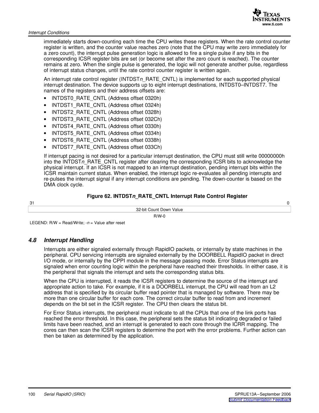
Figure 62. INTDSTn_RATE_CNTL Interrupt Rate Control Register
31 | 0 |
LEGEND: R/W = Read/Write;
4.8Interrupt Handling
Interrupts are either signaled externally through RapidIO packets, or internally by state machines in the peripheral. CPU servicing interrupts are signaled externally by the DOORBELL RapidIO packet in direct I/O mode, or internally by the CPPI module in the message passing mode. Error Status interrupts are signaled when error counting logic within the peripheral have reached their thresholds. In either case, it is the peripheral that signals the interrupt and sets the corresponding status bits.
When the CPU is interrupted, it reads the ICSR registers to determine the source of the interrupt and appropriate action to take. For example, if it is a DOORBELL interrupt, the CPU will read from an L2 address that is specified by its circular buffer read pointer that is managed by software. There may be more than one circular buffer for each core. The correct circular buffer to read from and increment depends on the bit set in the ICSR register. The CPU then clears the status bit.
For Error Status interrupts, the peripheral must indicate to all the CPUs that one of the link ports has reached the error threshold. In this case, the peripheral sets the status bit indicating degraded or failed limits have been reached, and an interrupt is generated to each core through the ICRR mapping. The cores can then scan the ICSR registers to determine the port with the error problems. Further action can then be taken as determined by the application.
100 | Serial RapidIO (SRIO) | SPRUE13A |