www.ti.com
SRIO Registers
5.92 Port IP Mode CSR (SP_IP_MODE)
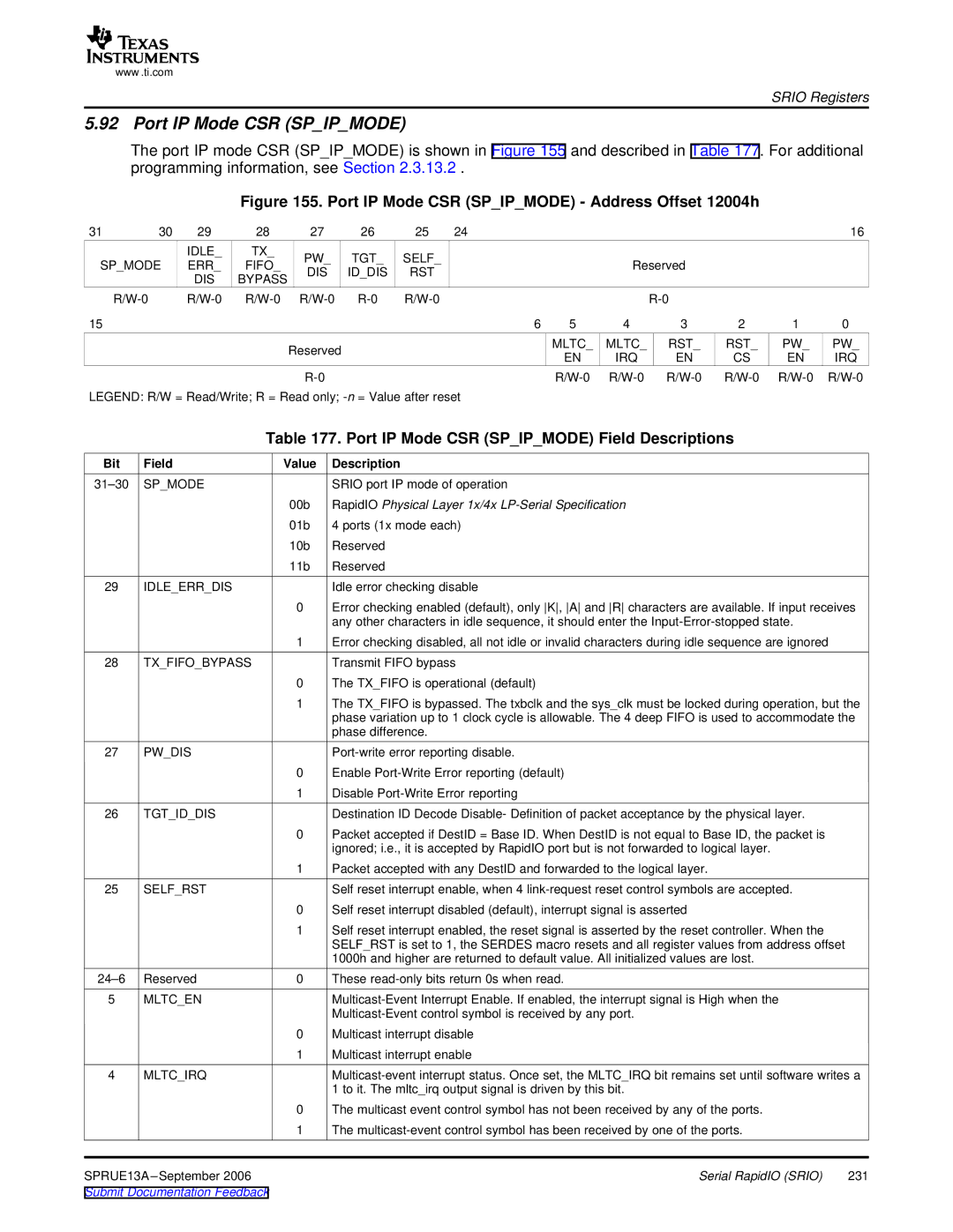
The port IP mode CSR (SP_IP_MODE) is shown in Figure 155 and described in Table 177. For additional programming information, see Section 2.3.13.2 .
Figure 155. Port IP Mode CSR (SP_IP_MODE) - Address Offset 12004h
31 | 30 | 29 | 28 | 27 | 26 | 25 | 24 |
|
|
|
|
| 16 |
|
| IDLE_ | TX_ | PW_ | TGT_ | SELF_ |
|
|
|
|
|
|
|
SP_MODE | ERR_ | FIFO_ |
|
| Reserved |
|
|
| |||||
DIS | ID_DIS | RST |
|
|
|
|
| ||||||
|
| DIS | BYPASS |
|
|
|
|
|
|
| |||
|
|
|
|
|
|
|
|
|
|
|
| ||
|
|
|
|
|
|
| |||||||
15 |
|
|
|
|
|
| 6 | 5 | 4 | 3 | 2 | 1 | 0 |
|
|
|
| Reserved |
|
|
| MLTC_ | MLTC_ | RST_ | RST_ | PW_ | PW_ |
|
|
|
|
|
|
| EN | IRQ | EN | CS | EN | IRQ | |
|
|
|
|
|
|
|
| ||||||
|
|
|
|
|
|
| |||||||
LEGEND: R/W = Read/Write; R = Read only; |
|
|
|
|
|
| |||||||
Table 177. Port IP Mode CSR (SP_IP_MODE) Field Descriptions
Bit | Field | Value | Description |
|
SP_MODE |
| SRIO port IP mode of operation |
| |
|
| 00b | RapidIO Physical Layer 1x/4x |
|
|
| 01b | 4 ports (1x mode each) |
|
|
| 10b | Reserved |
|
|
| 11b | Reserved |
|
29 | IDLE_ERR_DIS |
| Idle error checking disable |
|
|
| 0 | Error checking enabled (default), only K, A and R characters are available. If input receives | |
|
|
| any other characters in idle sequence, it should enter the |
|
|
| 1 | Error checking disabled, all not idle or invalid characters during idle sequence are ignored |
|
28 | TX_FIFO_BYPASS |
| Transmit FIFO bypass |
|
|
| 0 | The TX_FIFO is operational (default) |
|
|
| 1 | The TX_FIFO is bypassed. The txbclk and the sys_clk must be locked during operation, but the | |
|
|
| phase variation up to 1 clock cycle is allowable. The 4 deep FIFO is used to accommodate the | |
|
|
| phase difference. |
|
27 | PW_DIS |
|
| |
|
| 0 | Enable |
|
|
| 1 | Disable |
|
26 | TGT_ID_DIS |
| Destination ID Decode Disable- Definition of packet acceptance by the physical layer. |
|
|
| 0 | Packet accepted if DestID = Base ID. When DestID is not equal to Base ID, the packet is |
|
|
|
| ignored; i.e., it is accepted by RapidIO port but is not forwarded to logical layer. |
|
|
| 1 | Packet accepted with any DestID and forwarded to the logical layer. |
|
25 | SELF_RST |
| Self reset interrupt enable, when 4 |
|
|
| 0 | Self reset interrupt disabled (default), interrupt signal is asserted |
|
|
| 1 | Self reset interrupt enabled, the reset signal is asserted by the reset controller. When the |
|
|
|
| SELF_RST is set to 1, the SERDES macro resets and all register values from address offset |
|
|
|
| 1000h and higher are returned to default value. All initialized values are lost. |
|
Reserved | 0 | These |
| |
5 | MLTC_EN |
|
| |
|
|
|
| |
|
| 0 | Multicast interrupt disable |
|
|
| 1 | Multicast interrupt enable |
|
4 | MLTC_IRQ |
| ||
|
|
| 1 to it. The mltc_irq output signal is driven by this bit. |
|
|
| 0 | The multicast event control symbol has not been received by any of the ports. |
|
|
| 1 | The |
|
SPRUE13A |
| Serial RapidIO (SRIO) | 231 | |
Submit Documentation Feedback |
|
|
| |