www.ti.com
SRIO Functional Description
The clock recovery algorithms listed in the CDR bits operate to adjust the clocks used to sample the received message so that the data samples are taken midway between data transitions. The second order algorithm can be optionally disabled, and both can be configured to optimize their dynamics. Both algorithms use the same basic technique for determining whether the sampling clock is ideally placed, and if not whether it needs to be moved earlier or later. When two contiguous data samples are different, the phase sample between the two is examined. Eight data samples and nine phase samples are taken with each result counted as a vote to move the sample point either earlier or later. These eight data bits constitute the voting window. The eight votes are then counted, and an action to adjust the position of the sampling clock occurs if there is a majority of early or late votes. The first order algorithm makes a single phase adjustment per majority vote. The second order algorithm acts repeatedly according to the net difference between early and late majority votes, thereby adjusting for the rate of change of phase.
Setting the ALIGN field to 01 enables alignment to the K28 comma symbols included in the 8b:10b data encoding scheme defined by the IEEE and employed by numerous transmission standards. For systems which cannot use comma based symbol alignment, the single bit alignment jog capability provides a means to control the symbol realignment features of the receiver directly from logic implemented in the ASIC core. This logic can be designed to support whatever alignment detection protocol is required.
The EQ bits allow for enabling and configuring the adaptive equalizer incorporated in all of the receive channels, which can compensate for channel insertion loss by attenuating the low frequency components with respect to the high frequency components of the signal, thereby reducing
∙No adaptive equalization. The equalizer provides a flat response at the maximum gain. This setting may be appropriate if jitter at the receiver occurs predominantly as a result of crosstalk rather than frequency dependent loss.
∙Fully adaptive equalization. Both the low frequency gain and zero position of the equalizer are determined algorithmically by analysing the data patterns and transition positions in the received data. This setting should be used for most applications.
∙Partially adaptive equalisation. The low frequency gain of the equalizer is determined algorithmically by analysing the data patterns and transition positions in the received data. The zero position is fixed in one of eight zero positions. For any given application, the optimal setting is a function of the loss characteristics of the channel and the spectral density of the signal as well as the data rate, which means it is not possible to identify the best setting by data rate alone, although generally speaking, the lower the line rate, the lower the zero frequency that will be required.
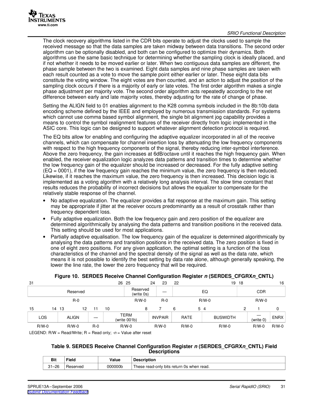
Figure 10. SERDES Receive Channel Configuration Register n (SERDES_CFGRXn_CNTL)
31 |
|
|
|
|
| 26 | 25 | 24 | 23 | 22 |
|
| 19 | 18 |
| 16 |
|
|
| Reserved |
|
|
| Reserved |
| — |
|
| EQ |
|
| CDR |
|
|
|
|
|
|
| (write 0s) |
|
|
|
|
|
| ||||
|
|
|
|
|
|
|
|
|
|
|
|
|
|
|
| |
|
|
|
|
|
|
|
|
|
|
| ||||||
15 | 14 | 13 | 12 | 11 | 10 |
| 8 |
| 7 | 6 | 5 | 4 |
| 2 | 1 | 0 |
LOS |
|
| ALIGN | — |
| TERM | INVPAIR |
| RATE |
| BUSWIDTH |
| — | ENRX | ||
|
|
| (write 001b) |
|
|
| (write 0) | |||||||||
|
|
|
|
|
|
|
|
|
|
|
|
|
| |||
|
|
|
|
|
| |||||||||||
LEGEND: R/W = Read/Write; R = Read only; |
|
|
|
|
|
|
|
| ||||||||
Table 9. SERDES Receive Channel Configuration Register n (SERDES_CFGRXn_CNTL) Field
Descriptions
Bit | Field | Value | Description |
|
Reserved | 000000b | These |
| |
SPRUE13A |
| Serial RapidIO (SRIO) | 31 | |
Submit Documentation Feedback |
|
|
| |