www.ti.com
SRIO Functional Description
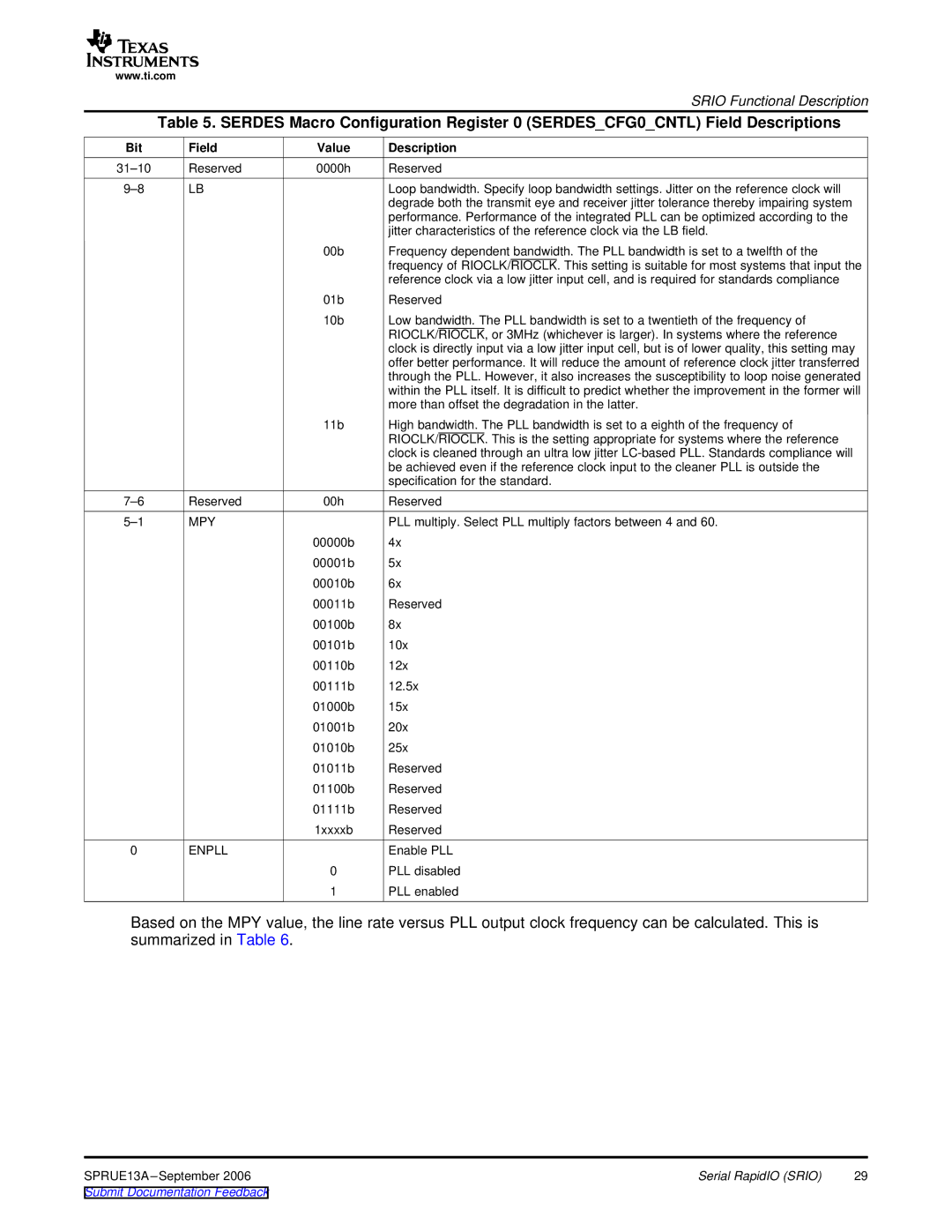
Table 5. SERDES Macro Configuration Register 0 (SERDES_CFG0_CNTL) Field Descriptions
Bit | Field | Value | Description |
Reserved | 0000h | Reserved | |
LB |
| Loop bandwidth. Specify loop bandwidth settings. Jitter on the reference clock will | |
|
|
| degrade both the transmit eye and receiver jitter tolerance thereby impairing system |
|
|
| performance. Performance of the integrated PLL can be optimized according to the |
|
|
| jitter characteristics of the reference clock via the LB field. |
|
| 00b | Frequency dependent bandwidth. The PLL bandwidth is set to a twelfth of the |
|
|
| frequency of RIOCLK/RIOCLK. This setting is suitable for most systems that input the |
|
|
| reference clock via a low jitter input cell, and is required for standards compliance |
|
| 01b | Reserved |
|
| 10b | Low bandwidth. The PLL bandwidth is set to a twentieth of the frequency of |
|
|
| RIOCLK/RIOCLK, or 3MHz (whichever is larger). In systems where the reference |
|
|
| clock is directly input via a low jitter input cell, but is of lower quality, this setting may |
|
|
| offer better performance. It will reduce the amount of reference clock jitter transferred |
|
|
| through the PLL. However, it also increases the susceptibility to loop noise generated |
|
|
| within the PLL itself. It is difficult to predict whether the improvement in the former will |
|
|
| more than offset the degradation in the latter. |
|
| 11b | High bandwidth. The PLL bandwidth is set to a eighth of the frequency of |
|
|
| RIOCLK/RIOCLK. This is the setting appropriate for systems where the reference |
|
|
| clock is cleaned through an ultra low jitter |
|
|
| be achieved even if the reference clock input to the cleaner PLL is outside the |
|
|
| specification for the standard. |
Reserved | 00h | Reserved | |
MPY |
| PLL multiply. Select PLL multiply factors between 4 and 60. | |
|
| 00000b | 4x |
|
| 00001b | 5x |
|
| 00010b | 6x |
|
| 00011b | Reserved |
|
| 00100b | 8x |
|
| 00101b | 10x |
|
| 00110b | 12x |
|
| 00111b | 12.5x |
|
| 01000b | 15x |
|
| 01001b | 20x |
|
| 01010b | 25x |
|
| 01011b | Reserved |
|
| 01100b | Reserved |
|
| 01111b | Reserved |
|
| 1xxxxb | Reserved |
0 | ENPLL |
| Enable PLL |
|
| 0 | PLL disabled |
|
| 1 | PLL enabled |
Based on the MPY value, the line rate versus PLL output clock frequency can be calculated. This is summarized in Table 6.
SPRUE13A | Serial RapidIO (SRIO) | 29 |