www.ti.com
SRIO Registers
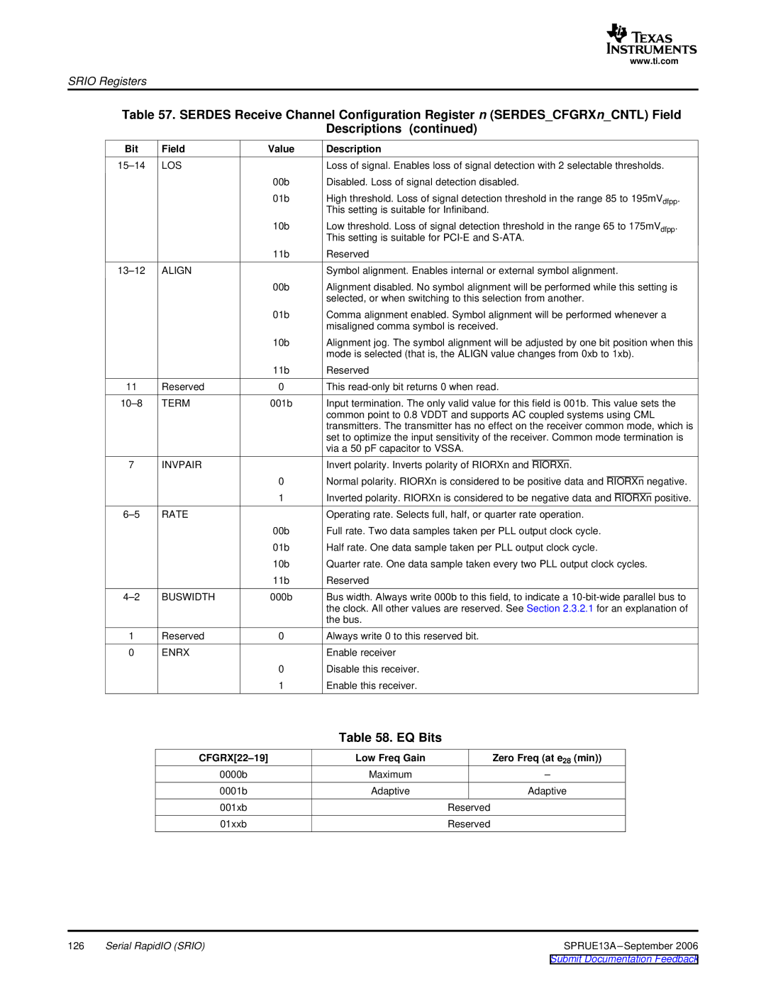
Table 57. SERDES Receive Channel Configuration Register n (SERDES_CFGRXn_CNTL) Field
Descriptions (continued)
Bit | Field | Value | Description |
LOS |
| Loss of signal. Enables loss of signal detection with 2 selectable thresholds. | |
|
| 00b | Disabled. Loss of signal detection disabled. |
|
| 01b | High threshold. Loss of signal detection threshold in the range 85 to 195mVdfpp. |
|
|
| This setting is suitable for Infiniband. |
|
| 10b | Low threshold. Loss of signal detection threshold in the range 65 to 175mVdfpp. |
|
|
| This setting is suitable for |
|
| 11b | Reserved |
ALIGN |
| Symbol alignment. Enables internal or external symbol alignment. | |
|
| 00b | Alignment disabled. No symbol alignment will be performed while this setting is |
|
|
| selected, or when switching to this selection from another. |
|
| 01b | Comma alignment enabled. Symbol alignment will be performed whenever a |
|
|
| misaligned comma symbol is received. |
|
| 10b | Alignment jog. The symbol alignment will be adjusted by one bit position when this |
|
|
| mode is selected (that is, the ALIGN value changes from 0xb to 1xb). |
|
| 11b | Reserved |
11 | Reserved | 0 | This |
TERM | 001b | Input termination. The only valid value for this field is 001b. This value sets the | |
|
|
| common point to 0.8 VDDT and supports AC coupled systems using CML |
|
|
| transmitters. The transmitter has no effect on the receiver common mode, which is |
|
|
| set to optimize the input sensitivity of the receiver. Common mode termination is |
|
|
| via a 50 pF capacitor to VSSA. |
7 | INVPAIR |
| Invert polarity. Inverts polarity of RIORXn and RIORXn. |
|
| 0 | Normal polarity. RIORXn is considered to be positive data and RIORXn negative. |
|
| 1 | Inverted polarity. RIORXn is considered to be negative data and RIORXn positive. |
RATE |
| Operating rate. Selects full, half, or quarter rate operation. | |
|
| 00b | Full rate. Two data samples taken per PLL output clock cycle. |
|
| 01b | Half rate. One data sample taken per PLL output clock cycle. |
|
| 10b | Quarter rate. One data sample taken every two PLL output clock cycles. |
|
| 11b | Reserved |
BUSWIDTH | 000b | Bus width. Always write 000b to this field, to indicate a | |
|
|
| the clock. All other values are reserved. See Section 2.3.2.1 for an explanation of |
|
|
| the bus. |
1 | Reserved | 0 | Always write 0 to this reserved bit. |
0 | ENRX |
| Enable receiver |
|
| 0 | Disable this receiver. |
|
| 1 | Enable this receiver. |
Table 58. EQ Bits
| Low Freq Gain | Zero Freq (at e28 (min)) |
0000b | Maximum | – |
0001b | Adaptive | Adaptive |
001xb |
| Reserved |
01xxb |
| Reserved |
126 | Serial RapidIO (SRIO) | SPRUE13A |