www.ti.com
Interrupt Conditions
Table 35. Interrupt Condition Status and Clear Bits
Field | Access | Reset Value | Value | Function |
ICSx | R | 0 | 0 | Condition not present |
|
|
| 1 | Condition present |
ICCx | W | 0 | 0 | No effect |
|
|
| 1 | Clear the condition status bit (ICSx) |
4.3.1Doorbell Interrupt Condition Status and Clear Registers
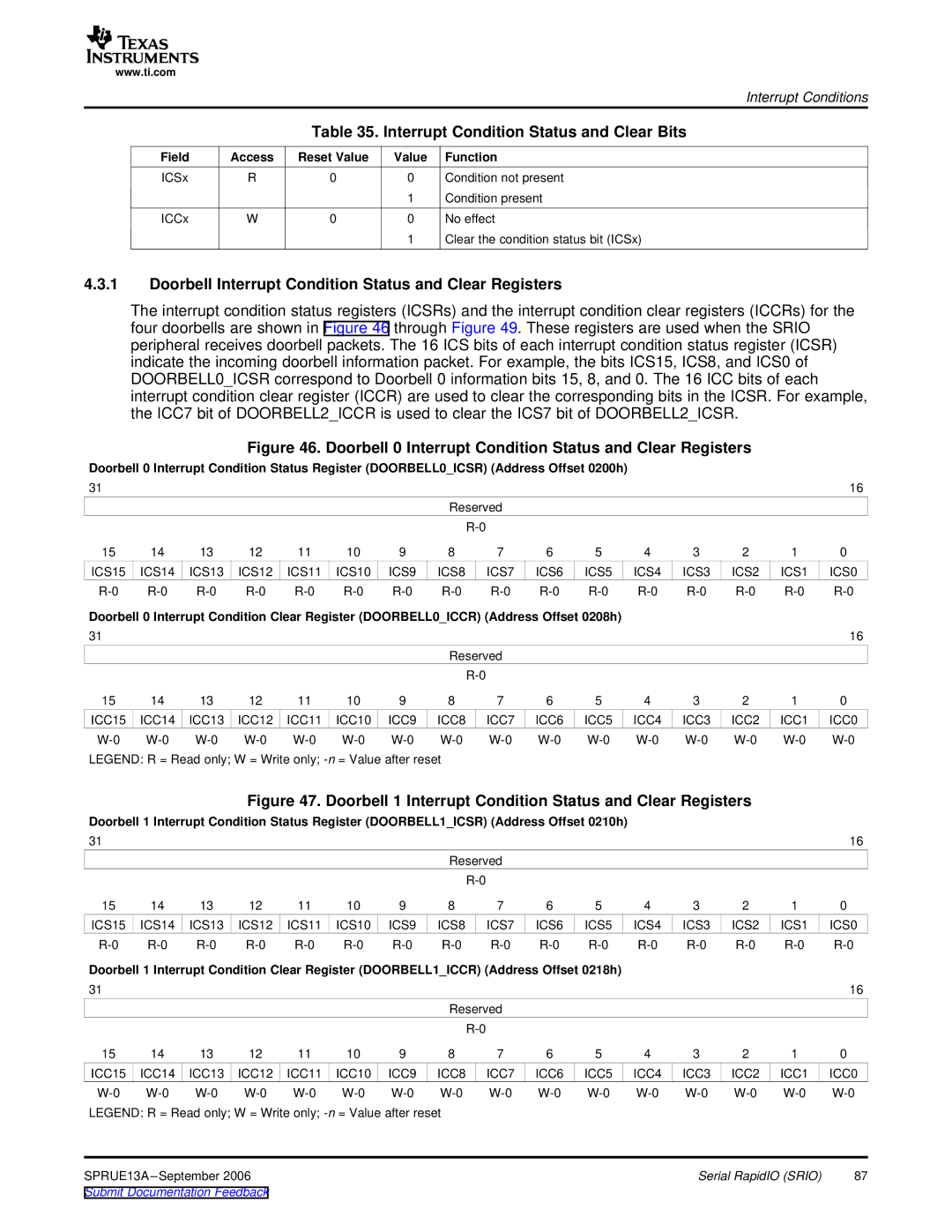
The interrupt condition status registers (ICSRs) and the interrupt condition clear registers (ICCRs) for the four doorbells are shown in Figure 46 through Figure 49. These registers are used when the SRIO peripheral receives doorbell packets. The 16 ICS bits of each interrupt condition status register (ICSR) indicate the incoming doorbell information packet. For example, the bits ICS15, ICS8, and ICS0 of DOORBELL0_ICSR correspond to Doorbell 0 information bits 15, 8, and 0. The 16 ICC bits of each interrupt condition clear register (ICCR) are used to clear the corresponding bits in the ICSR. For example, the ICC7 bit of DOORBELL2_ICCR is used to clear the ICS7 bit of DOORBELL2_ICSR.
Figure 46. Doorbell 0 Interrupt Condition Status and Clear Registers
Doorbell 0 Interrupt Condition Status Register (DOORBELL0_ICSR) (Address Offset 0200h)
31 |
|
|
|
|
|
|
|
|
|
|
|
|
|
| 16 |
|
|
|
|
|
|
| Reserved |
|
|
|
|
|
|
| |
|
|
|
|
|
|
|
|
|
|
|
|
|
|
| |
15 | 14 | 13 | 12 | 11 | 10 | 9 | 8 | 7 | 6 | 5 | 4 | 3 | 2 | 1 | 0 |
ICS15 | ICS14 | ICS13 | ICS12 | ICS11 | ICS10 | ICS9 | ICS8 | ICS7 | ICS6 | ICS5 | ICS4 | ICS3 | ICS2 | ICS1 | ICS0 |
Doorbell 0 Interrupt Condition Clear Register (DOORBELL0_ICCR) (Address Offset 0208h) |
|
|
|
|
| ||||||||||
31 |
|
|
|
|
|
|
|
|
|
|
|
|
|
| 16 |
|
|
|
|
|
|
| Reserved |
|
|
|
|
|
|
| |
|
|
|
|
|
|
|
|
|
|
|
|
|
|
| |
15 | 14 | 13 | 12 | 11 | 10 | 9 | 8 | 7 | 6 | 5 | 4 | 3 | 2 | 1 | 0 |
ICC15 | ICC14 | ICC13 | ICC12 | ICC11 | ICC10 | ICC9 | ICC8 | ICC7 | ICC6 | ICC5 | ICC4 | ICC3 | ICC2 | ICC1 | ICC0 |
LEGEND: R = Read only; W = Write only;
Figure 47. Doorbell 1 Interrupt Condition Status and Clear Registers
Doorbell 1 Interrupt Condition Status Register (DOORBELL1_ICSR) (Address Offset 0210h) |
|
|
|
|
| ||||||||||
31 |
|
|
|
|
|
|
|
|
|
|
|
|
|
| 16 |
|
|
|
|
|
|
| Reserved |
|
|
|
|
|
|
| |
|
|
|
|
|
|
|
|
|
|
|
|
|
|
| |
15 | 14 | 13 | 12 | 11 | 10 | 9 | 8 | 7 | 6 | 5 | 4 | 3 | 2 | 1 | 0 |
ICS15 | ICS14 | ICS13 | ICS12 | ICS11 | ICS10 | ICS9 | ICS8 | ICS7 | ICS6 | ICS5 | ICS4 | ICS3 | ICS2 | ICS1 | ICS0 |
Doorbell 1 Interrupt Condition Clear Register (DOORBELL1_ICCR) (Address Offset 0218h) |
|
|
|
|
| ||||||||||
31 |
|
|
|
|
|
|
|
|
|
|
|
|
|
| 16 |
|
|
|
|
|
|
| Reserved |
|
|
|
|
|
|
| |
|
|
|
|
|
|
|
|
|
|
|
|
|
|
| |
15 | 14 | 13 | 12 | 11 | 10 | 9 | 8 | 7 | 6 | 5 | 4 | 3 | 2 | 1 | 0 |
ICC15 | ICC14 | ICC13 | ICC12 | ICC11 | ICC10 | ICC9 | ICC8 | ICC7 | ICC6 | ICC5 | ICC4 | ICC3 | ICC2 | ICC1 | ICC0 |
LEGEND: R = Read only; W = Write only; |
|
|
|
|
|
|
|
| |||||||
SPRUE13A |
|
|
|
|
|
|
|
| Serial RapidIO (SRIO) | 87 | |||||
Submit Documentation Feedback |
|
|
|
|
|
|
|
|
|
|
|
| |||