www.ti.com
SRIO Functional Description
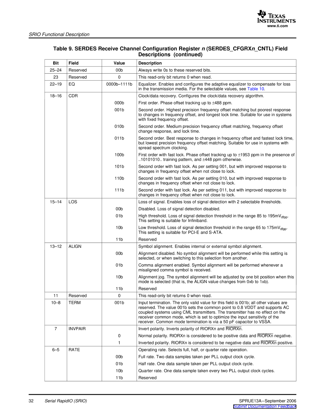
Table 9. SERDES Receive Channel Configuration Register n (SERDES_CFGRXn_CNTL) Field
Descriptions (continued)
| Bit | Field | Value | Description |
| Reserved | 00b | Always write 0s to these reserved bits. | |
| 23 | Reserved | 0 | This |
| EQ | Equalizer. Enables and configures the adaptive equalizer to compensate for loss | ||
|
|
|
| in the transmission media. For the selectable values, see Table 10. |
| CDR |
| Clock/data recovery. Configures the clock/data recovery algorithm. | |
|
|
| 000b | First order. Phase offset tracking up to ±488 ppm. |
|
|
| 001b | Second order. Highest precision frequency offset matching but poorest response |
|
|
|
| to changes in frequency offset, and longest lock time. Suitable for use in systems |
|
|
|
| with fixed frequency offset. |
|
|
| 010b | Second order. Medium precision frequency offset matching, frequency offset |
|
|
|
| change response, and lock time. |
|
|
| 011b | Second order. Best response to changes in frequency offset and fastest lock time, |
|
|
|
| but lowest precision frequency offset matching. Suitable for use in systems with |
|
|
|
| spread spectrum clocking. |
|
|
| 100b | First order with fast lock. Phase offset tracking up to ±1953 ppm in the presence of |
|
|
|
| ..10101010.. training pattern, and ±448 ppm otherwise. |
|
|
| 101b | Second order with fast lock. As per setting 001, but with improved response to |
|
|
|
| changes in frequency offset when not close to lock. |
|
|
| 110b | Second order with fast lock. As per setting 010, but with improved response to |
|
|
|
| changes in frequency offset when not close to lock. |
|
|
| 111b | Second order with fast lock. As per setting 011, but with improved response to |
|
|
|
| changes in frequency offset when not close to lock. |
| LOS |
| Loss of signal. Enables loss of signal detection with 2 selectable thresholds. | |
|
|
| 00b | Disabled. Loss of signal detection disabled. |
|
|
| 01b | High threshold. Loss of signal detection threshold in the range 85 to 195mVdfpp. |
|
|
|
| This setting is suitable for Infiniband. |
|
|
| 10b | Low threshold. Loss of signal detection threshold in the range 65 to 175mVdfpp. |
|
|
|
| This setting is suitable for |
|
|
| 11b | Reserved |
| ALIGN |
| Symbol alignment. Enables internal or external symbol alignment. | |
|
|
| 00b | Alignment disabled. No symbol alignment will be performed while this setting is |
|
|
|
| selected, or when switching to this selection from another. |
|
|
| 01b | Comma alignment enabled. Symbol alignment will be performed whenever a |
|
|
|
| misaligned comma symbol is received. |
|
|
| 10b | Alignment jog. The symbol alignment will be adjusted by one bit position when this |
|
|
|
| mode is selected (that is, the ALIGN value changes from 0xb to 1xb). |
|
|
| 11b | Reserved |
| 11 | Reserved | 0 | This |
| TERM | 001b | Input termination. The only valid value for this field is 001b; all other values are | |
|
|
|
| reserved. The value 001b sets the common point to 0.8 VDDT and supports AC |
|
|
|
| coupled systems using CML transmitters. The transmitter has no effect on the |
|
|
|
| receiver common mode, which is set to optimize the input sensitivity of the |
|
|
|
| receiver. Common mode termination is via a 50 pF capacitor to VSSA. |
| 7 | INVPAIR |
| Invert polarity. Inverts polarity of RIORXn and RIORXn. |
|
|
| 0 | Normal polarity. RIORXn is considered to be positive data and RIORXn negative. |
|
|
| 1 | Inverted polarity. RIORXn is considered to be negative data and RIORXn positive. |
| RATE |
| Operating rate. Selects full, half, or quarter rate operation. | |
|
|
| 00b | Full rate. Two data samples taken per PLL output clock cycle. |
|
|
| 01b | Half rate. One data sample taken per PLL output clock cycle. |
|
|
| 10b | Quarter rate. One data sample taken every two PLL output clock cycles. |
|
|
| 11b | Reserved |
32 | Serial RapidIO (SRIO) |
| SPRUE13A | |