www.ti.com
Interrupt Conditions
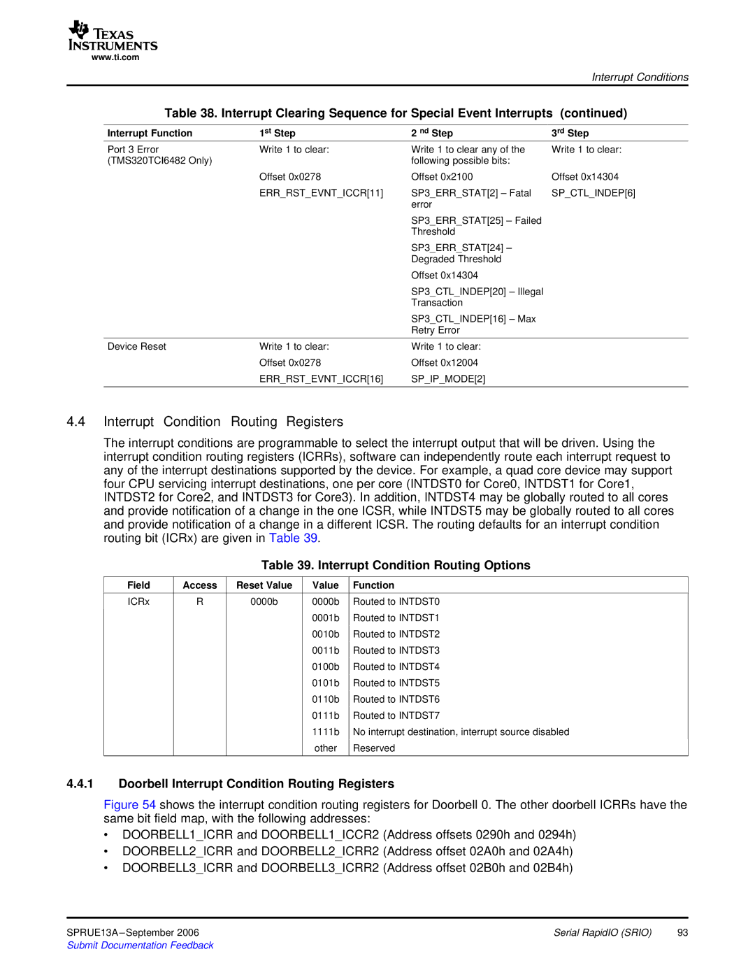
Table 38. Interrupt Clearing Sequence for Special Event Interrupts (continued)
Interrupt Function | 1st Step | 2 nd Step | 3rd Step |
Port 3 Error | Write 1 to clear: | Write 1 to clear any of the | Write 1 to clear: |
(TMS320TCI6482 Only) |
| following possible bits: |
|
| Offset 0x0278 | Offset 0x2100 | Offset 0x14304 |
| ERR_RST_EVNT_ICCR[11] | SP3_ERR_STAT[2] – Fatal | SP_CTL_INDEP[6] |
|
| error |
|
|
| SP3_ERR_STAT[25] – Failed |
|
|
| Threshold |
|
|
| SP3_ERR_STAT[24] – |
|
|
| Degraded Threshold |
|
|
| Offset 0x14304 |
|
|
| SP3_CTL_INDEP[20] – Illegal |
|
|
| Transaction |
|
|
| SP3_CTL_INDEP[16] – Max |
|
|
| Retry Error |
|
Device Reset | Write 1 to clear: | Write 1 to clear: |
|
| Offset 0x0278 | Offset 0x12004 |
|
| ERR_RST_EVNT_ICCR[16] | SP_IP_MODE[2] |
|
4.4Interrupt Condition Routing Registers
The interrupt conditions are programmable to select the interrupt output that will be driven. Using the interrupt condition routing registers (ICRRs), software can independently route each interrupt request to any of the interrupt destinations supported by the device. For example, a quad core device may support four CPU servicing interrupt destinations, one per core (INTDST0 for Core0, INTDST1 for Core1, INTDST2 for Core2, and INTDST3 for Core3). In addition, INTDST4 may be globally routed to all cores and provide notification of a change in the one ICSR, while INTDST5 may be globally routed to all cores and provide notification of a change in a different ICSR. The routing defaults for an interrupt condition routing bit (ICRx) are given in Table 39.
Table 39. Interrupt Condition Routing Options
Field | Access | Reset Value | Value | Function |
ICRx | R | 0000b | 0000b | Routed to INTDST0 |
|
|
| 0001b | Routed to INTDST1 |
|
|
| 0010b | Routed to INTDST2 |
|
|
| 0011b | Routed to INTDST3 |
|
|
| 0100b | Routed to INTDST4 |
|
|
| 0101b | Routed to INTDST5 |
|
|
| 0110b | Routed to INTDST6 |
|
|
| 0111b | Routed to INTDST7 |
|
|
| 1111b | No interrupt destination, interrupt source disabled |
|
|
| other | Reserved |
4.4.1Doorbell Interrupt Condition Routing Registers
Figure 54 shows the interrupt condition routing registers for Doorbell 0. The other doorbell ICRRs have the same bit field map, with the following addresses:
∙DOORBELL1_ICRR and DOORBELL1_ICCR2 (Address offsets 0290h and 0294h)
∙DOORBELL2_ICRR and DOORBELL2_ICRR2 (Address offset 02A0h and 02A4h)
∙DOORBELL3_ICRR and DOORBELL3_ICRR2 (Address offset 02B0h and 02B4h)
SPRUE13A | Serial RapidIO (SRIO) | 93 |
