www.ti.com
Interrupt Conditions
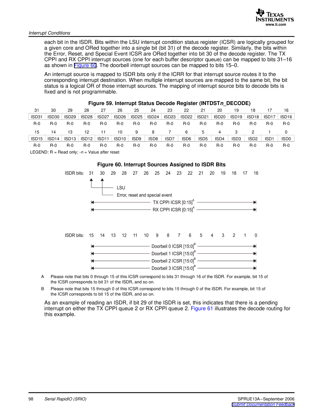
each bit in the ISDR. Bits within the LSU interrupt condition status register (ICSR) are logically grouped for a given core and ORed together into a single bit (bit 31) of the decode register. Similarly, the bits within the Error, Reset, and Special Event ICSR are ORed together into bit 30 of the decode register. The TX CPPI and RX CPPI interrupt sources (one for each buffer descriptor queue) can be mapped to bits
An interrupt source is mapped to ISDR bits only if the ICRR for that interrupt source routes it to the corresponding interrupt destination. When multiple interrupt sources are mapped to the same bit, the bit status is a logical OR of those interrupt sources. The mapping of interrupt source bits to decode bits is fixed and is not programmable.
Figure 59. Interrupt Status Decode Register (INTDSTn_DECODE)
31 | 30 | 29 | 28 | 27 | 26 | 25 | 24 | 23 | 22 | 21 | 20 | 19 | 18 | 17 | 16 |
ISD31 | ISD30 | ISD29 | ISD28 | ISD27 | ISD26 | ISD25 | ISD24 | ISD23 | ISD22 | ISD21 | ISD20 | ISD19 | ISD18 | ISD17 | ISD16 |
15 | 14 | 13 | 12 | 11 | 10 | 9 | 8 | 7 | 6 | 5 | 4 | 3 | 2 | 1 | 0 |
ISD15 | ISD14 | ISD13 | ISD12 | ISD11 | ISD10 | ISD9 | ISD8 | ISD7 | ISD6 | ISD5 | ISD4 | ISD3 | ISD2 | ISD1 | ISD0 |
LEGEND: R = Read only;
Figure 60. Interrupt Sources Assigned to ISDR Bits
APlease note that bits 0 through 15 of this ICSR correspond to bits 31 through 16 of the ISDR. For example, bit 15 of the ICSR corresponds to bit 31 of the ISDR, and so on.
BPlease note that bits 15 through 0 of this ICSR correspond to bits 15 through 0 of the ISDR. For example, bit 15 of the ICSR corresponds to bit 15 of the ISDR, and so on.
As an example of reading an ISDR, if bit 29 of the ISDR is set, this indicates that there is a pending interrupt on either the TX CPPI queue 2 or RX CPPI queue 2. Figure 61 illustrates the decode routing for this example.
98 | Serial RapidIO (SRIO) | SPRUE13A |
