www.ti.com
SRIO Registers
5.14 SERDES Transmit Channel Configuration Register n (SERDES_CFGTXn_CNTL)
There are four of these registers, to support four ports (see Table 59). The general form for a SERDES transmit channel configuration register is summarized by Figure 75 and Table 60. See Section 2.3.2.3 for a complete explanation of the programming for these registers.
Table 59. SERDES_CFGTXn_CNTL Registers and the Associated Ports
Register | Address Offset | Associated Port |
SERDES_CFGTX0_CNTL | 0110h | Port 0 |
SERDES_CFGTX1_CNTL | 0114h | Port 1 |
SERDES_CFGTX2_CNTL | 0118h | Port 2 (TMS320TCI6482 Only) |
SERDES_CFGTX3_CNTL | 011Ch | Port 3 (TMS320TCI6482 Only) |
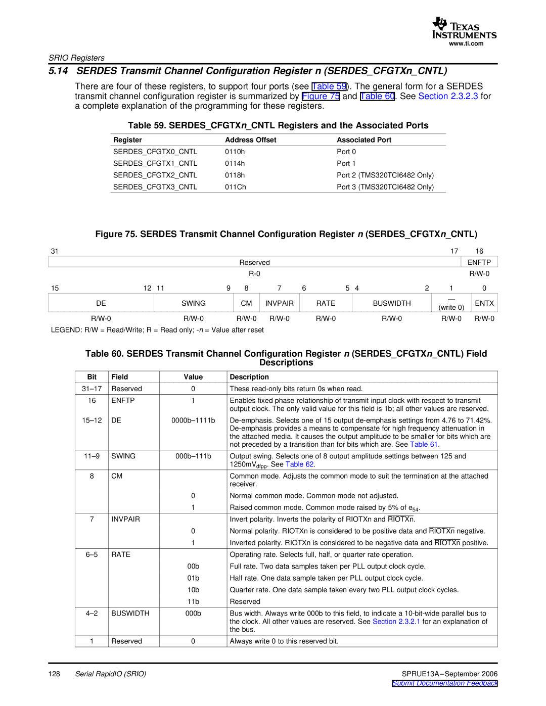
Figure 75. SERDES Transmit Channel Configuration Register n (SERDES_CFGTXn_CNTL)
31 |
|
|
|
|
|
|
|
|
| 17 | 16 |
|
|
|
| Reserved |
|
|
|
|
| ENFTP | |
|
|
|
|
|
|
|
|
|
| ||
15 | 12 | 11 | 9 | 8 | 7 | 6 | 5 | 4 | 2 | 1 | 0 |
DE |
| SWING |
| CM | INVPAIR | RATE |
| BUSWIDTH |
| — | ENTX |
|
|
|
| (write 0) | |||||||
|
|
|
|
|
|
|
|
|
|
| |
|
|
|
| ||||||||
LEGEND: R/W = Read/Write; R = Read only; |
|
|
|
|
|
|
| ||||
Table 60. SERDES Transmit Channel Configuration Register n (SERDES_CFGTXn_CNTL) Field
Descriptions
| Bit | Field | Value | Description |
| Reserved | 0 | These | |
| 16 | ENFTP | 1 | Enables fixed phase relationship of transmit input clock with respect to transmit |
|
|
|
| output clock. The only valid value for this field is 1b; all other values are reserved. |
| DE | |||
|
|
|
| |
|
|
|
| the attached media. It causes the output amplitude to be smaller for bits which are |
|
|
|
| not preceded by a transition than for bits which are. See Table 61. |
| SWING | Output swing. Selects one of 8 output amplitude settings between 125 and | ||
|
|
|
| 1250mVdfpp. See Table 62. |
| 8 | CM |
| Common mode. Adjusts the common mode to suit the termination at the attached |
|
|
|
| receiver. |
|
|
| 0 | Normal common mode. Common mode not adjusted. |
|
|
| 1 | Raised common mode. Common mode raised by 5% of e54. |
| 7 | INVPAIR |
| Invert polarity. Inverts the polarity of RIOTXn and RIOTXn. |
|
|
| 0 | Normal polarity. RIOTXn is considered to be positive data and RIOTXn negative. |
|
|
| 1 | Inverted polarity. RIOTXn is considered to be negative data and RIOTXn positive. |
| RATE |
| Operating rate. Selects full, half, or quarter rate operation. | |
|
|
| 00b | Full rate. Two data samples taken per PLL output clock cycle. |
|
|
| 01b | Half rate. One data sample taken per PLL output clock cycle. |
|
|
| 10b | Quarter rate. One data sample taken every two PLL output clock cycles. |
|
|
| 11b | Reserved |
| BUSWIDTH | 000b | Bus width. Always write 000b to this field, to indicate a | |
|
|
|
| the clock. All other values are reserved. See Section 2.3.2.1 for an explanation of |
|
|
|
| the bus. |
| 1 | Reserved | 0 | Always write 0 to this reserved bit. |
128 | Serial RapidIO (SRIO) |
| SPRUE13A | |