www.ti.com
SRIO Registers
5.4Peripheral Settings Control Register (PER_SET_CNTL)
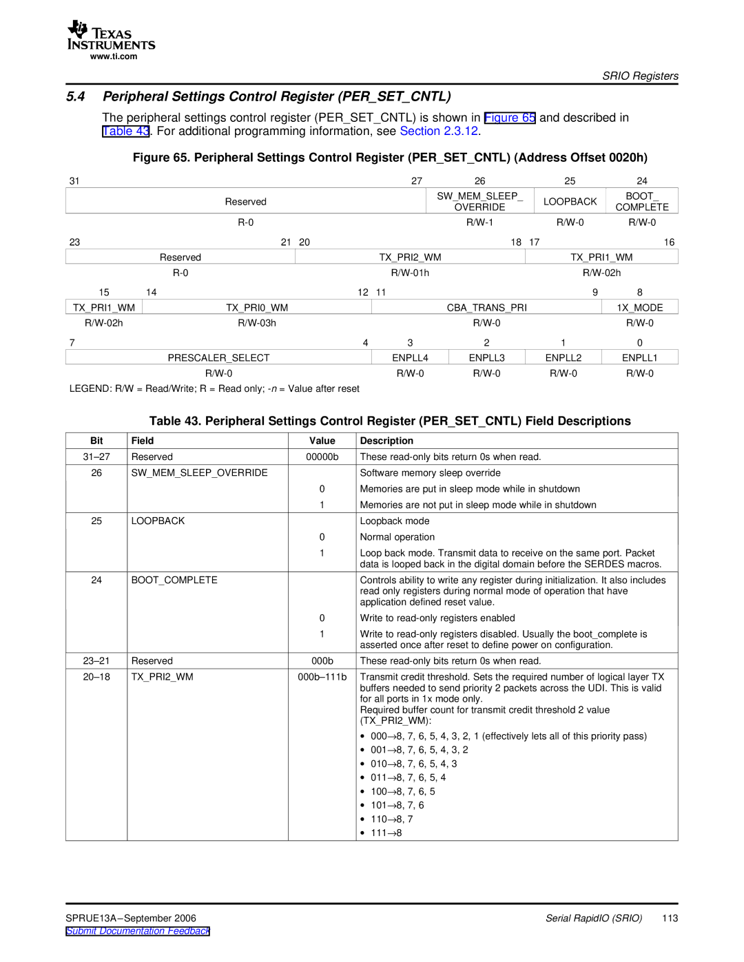
The peripheral settings control register (PER_SET_CNTL) is shown in Figure 65 and described in Table 43. For additional programming information, see Section 2.3.12.
Figure 65. Peripheral Settings Control Register (PER_SET_CNTL) (Address Offset 0020h)
31 |
|
|
| 27 | 26 |
| 25 | 24 |
|
| Reserved |
|
| SW_MEM_SLEEP_ |
| LOOPBACK | BOOT_ |
|
|
|
| OVERRIDE |
| COMPLETE | ||
|
|
|
|
|
|
| ||
|
|
|
|
| ||||
23 |
| 21 | 20 |
| 18 | 17 |
| 16 |
|
| Reserved |
| TX_PRI2_WM |
| TX_PRI1_WM | ||
|
|
|
|
| ||||
15 | 14 |
| 12 | 11 |
|
| 9 | 8 |
TX_PRI1_WM |
| TX_PRI0_WM |
|
| CBA_TRANS_PRI |
|
| 1X_MODE |
|
|
|
|
| ||||
7 |
|
| 4 | 3 | 2 |
| 1 | 0 |
|
| PRESCALER_SELECT |
| ENPLL4 | ENPLL3 |
| ENPLL2 | ENPLL1 |
|
|
|
| |||||
LEGEND: R/W = Read/Write; R = Read only; |
|
|
|
|
| |||
Table 43. Peripheral Settings Control Register (PER_SET_CNTL) Field Descriptions
Bit | Field | Value | Description |
Reserved | 00000b | These | |
26 | SW_MEM_SLEEP_OVERRIDE |
| Software memory sleep override |
|
| 0 | Memories are put in sleep mode while in shutdown |
|
| 1 | Memories are not put in sleep mode while in shutdown |
25 | LOOPBACK |
| Loopback mode |
|
| 0 | Normal operation |
|
| 1 | Loop back mode. Transmit data to receive on the same port. Packet |
|
|
| data is looped back in the digital domain before the SERDES macros. |
24 | BOOT_COMPLETE |
| Controls ability to write any register during initialization. It also includes |
|
|
| read only registers during normal mode of operation that have |
|
|
| application defined reset value. |
|
| 0 | Write to |
|
| 1 | Write to |
|
|
| asserted once after reset to define power on configuration. |
Reserved | 000b | These | |
TX_PRI2_WM | Transmit credit threshold. Sets the required number of logical layer TX | ||
|
|
| buffers needed to send priority 2 packets across the UDI. This is valid |
|
|
| for all ports in 1x mode only. |
|
|
| Required buffer count for transmit credit threshold 2 value |
|
|
| (TX_PRI2_WM): |
∙ 000→8, 7, 6, 5, 4, 3, 2, 1 (effectively lets all of this priority pass) ∙ 001→8, 7, 6, 5, 4, 3, 2 ∙ 010→8, 7, 6, 5, 4, 3 ∙ 011→8, 7, 6, 5, 4 ∙ 100→8, 7, 6, 5 ∙ 101→8, 7, 6 ∙ 110→8, 7 ∙ 111→8
SPRUE13A | Serial RapidIO (SRIO) | 113 |
Submit Documentation Feedback |
|
|