www.ti.com
SRIO Registers
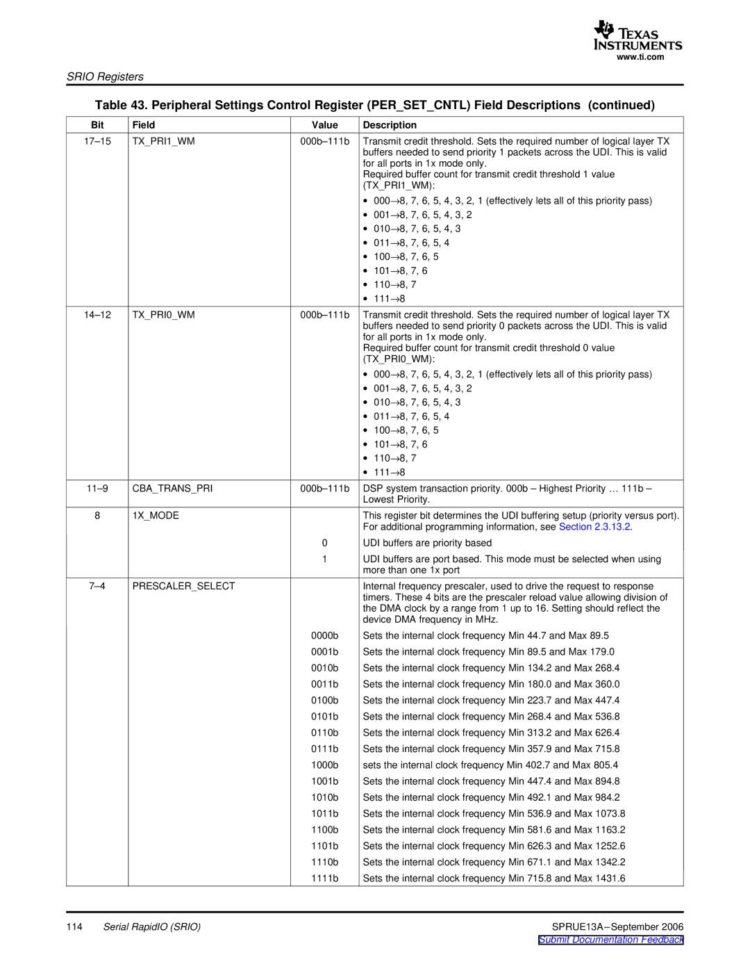
Table 43. Peripheral Settings Control Register (PER_SET_CNTL) Field Descriptions (continued)
| Bit | Field | Value | Description |
| TX_PRI1_WM | Transmit credit threshold. Sets the required number of logical layer TX | ||
|
|
|
| buffers needed to send priority 1 packets across the UDI. This is valid |
|
|
|
| for all ports in 1x mode only. |
|
|
|
| Required buffer count for transmit credit threshold 1 value |
|
|
|
| (TX_PRI1_WM): |
|
|
|
| ∙ 000→8, 7, 6, 5, 4, 3, 2, 1 (effectively lets all of this priority pass) |
|
|
|
| ∙ 001→8, 7, 6, 5, 4, 3, 2 |
|
|
|
| ∙ 010→8, 7, 6, 5, 4, 3 |
|
|
|
| ∙ 011→8, 7, 6, 5, 4 |
|
|
|
| ∙ 100→8, 7, 6, 5 |
|
|
|
| ∙ 101→8, 7, 6 |
|
|
|
| ∙ 110→8, 7 |
|
|
|
| ∙ 111→8 |
| TX_PRI0_WM | Transmit credit threshold. Sets the required number of logical layer TX | ||
|
|
|
| buffers needed to send priority 0 packets across the UDI. This is valid |
|
|
|
| for all ports in 1x mode only. |
|
|
|
| Required buffer count for transmit credit threshold 0 value |
|
|
|
| (TX_PRI0_WM): |
|
|
|
| ∙ 000→8, 7, 6, 5, 4, 3, 2, 1 (effectively lets all of this priority pass) |
|
|
|
| ∙ 001→8, 7, 6, 5, 4, 3, 2 |
|
|
|
| ∙ 010→8, 7, 6, 5, 4, 3 |
|
|
|
| ∙ 011→8, 7, 6, 5, 4 |
|
|
|
| ∙ 100→8, 7, 6, 5 |
|
|
|
| ∙ 101→8, 7, 6 |
|
|
|
| ∙ 110→8, 7 |
|
|
|
| ∙ 111→8 |
| CBA_TRANS_PRI | DSP system transaction priority. 000b – Highest Priority … 111b – | ||
|
|
|
| Lowest Priority. |
| 8 | 1X_MODE |
| This register bit determines the UDI buffering setup (priority versus port). |
|
|
|
| For additional programming information, see Section 2.3.13.2. |
|
|
| 0 | UDI buffers are priority based |
|
|
| 1 | UDI buffers are port based. This mode must be selected when using |
|
|
|
| more than one 1x port |
| PRESCALER_SELECT |
| Internal frequency prescaler, used to drive the request to response | |
|
|
|
| timers. These 4 bits are the prescaler reload value allowing division of |
|
|
|
| the DMA clock by a range from 1 up to 16. Setting should reflect the |
|
|
|
| device DMA frequency in MHz. |
|
|
| 0000b | Sets the internal clock frequency Min 44.7 and Max 89.5 |
|
|
| 0001b | Sets the internal clock frequency Min 89.5 and Max 179.0 |
|
|
| 0010b | Sets the internal clock frequency Min 134.2 and Max 268.4 |
|
|
| 0011b | Sets the internal clock frequency Min 180.0 and Max 360.0 |
|
|
| 0100b | Sets the internal clock frequency Min 223.7 and Max 447.4 |
|
|
| 0101b | Sets the internal clock frequency Min 268.4 and Max 536.8 |
|
|
| 0110b | Sets the internal clock frequency Min 313.2 and Max 626.4 |
|
|
| 0111b | Sets the internal clock frequency Min 357.9 and Max 715.8 |
|
|
| 1000b | sets the internal clock frequency Min 402.7 and Max 805.4 |
|
|
| 1001b | Sets the internal clock frequency Min 447.4 and Max 894.8 |
|
|
| 1010b | Sets the internal clock frequency Min 492.1 and Max 984.2 |
|
|
| 1011b | Sets the internal clock frequency Min 536.9 and Max 1073.8 |
|
|
| 1100b | Sets the internal clock frequency Min 581.6 and Max 1163.2 |
|
|
| 1101b | Sets the internal clock frequency Min 626.3 and Max 1252.6 |
|
|
| 1110b | Sets the internal clock frequency Min 671.1 and Max 1342.2 |
|
|
| 1111b | Sets the internal clock frequency Min 715.8 and Max 1431.6 |
114 | Serial RapidIO (SRIO) |
| SPRUE13A | |