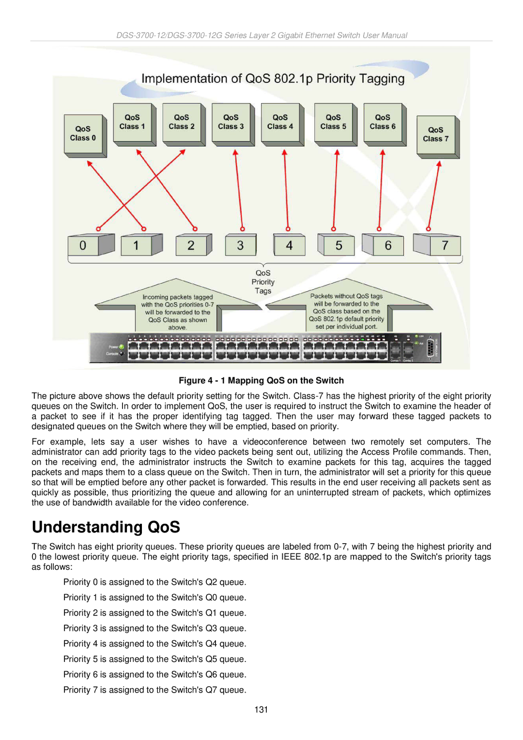
Figure 4 - 1 Mapping QoS on the Switch
The picture above shows the default priority setting for the Switch.
For example, lets say a user wishes to have a videoconference between two remotely set computers. The administrator can add priority tags to the video packets being sent out, utilizing the Access Profile commands. Then, on the receiving end, the administrator instructs the Switch to examine packets for this tag, acquires the tagged packets and maps them to a class queue on the Switch. Then in turn, the administrator will set a priority for this queue so that will be emptied before any other packet is forwarded. This results in the end user receiving all packets sent as quickly as possible, thus prioritizing the queue and allowing for an uninterrupted stream of packets, which optimizes the use of bandwidth available for the video conference.
Understanding QoS
The Switch has eight priority queues. These priority queues are labeled from
Priority 0 is assigned to the Switch's Q2 queue. Priority 1 is assigned to the Switch's Q0 queue. Priority 2 is assigned to the Switch's Q1 queue. Priority 3 is assigned to the Switch's Q3 queue. Priority 4 is assigned to the Switch's Q4 queue. Priority 5 is assigned to the Switch's Q5 queue. Priority 6 is assigned to the Switch's Q6 queue. Priority 7 is assigned to the Switch's Q7 queue.
131