|
|
| |
|
|
|
|
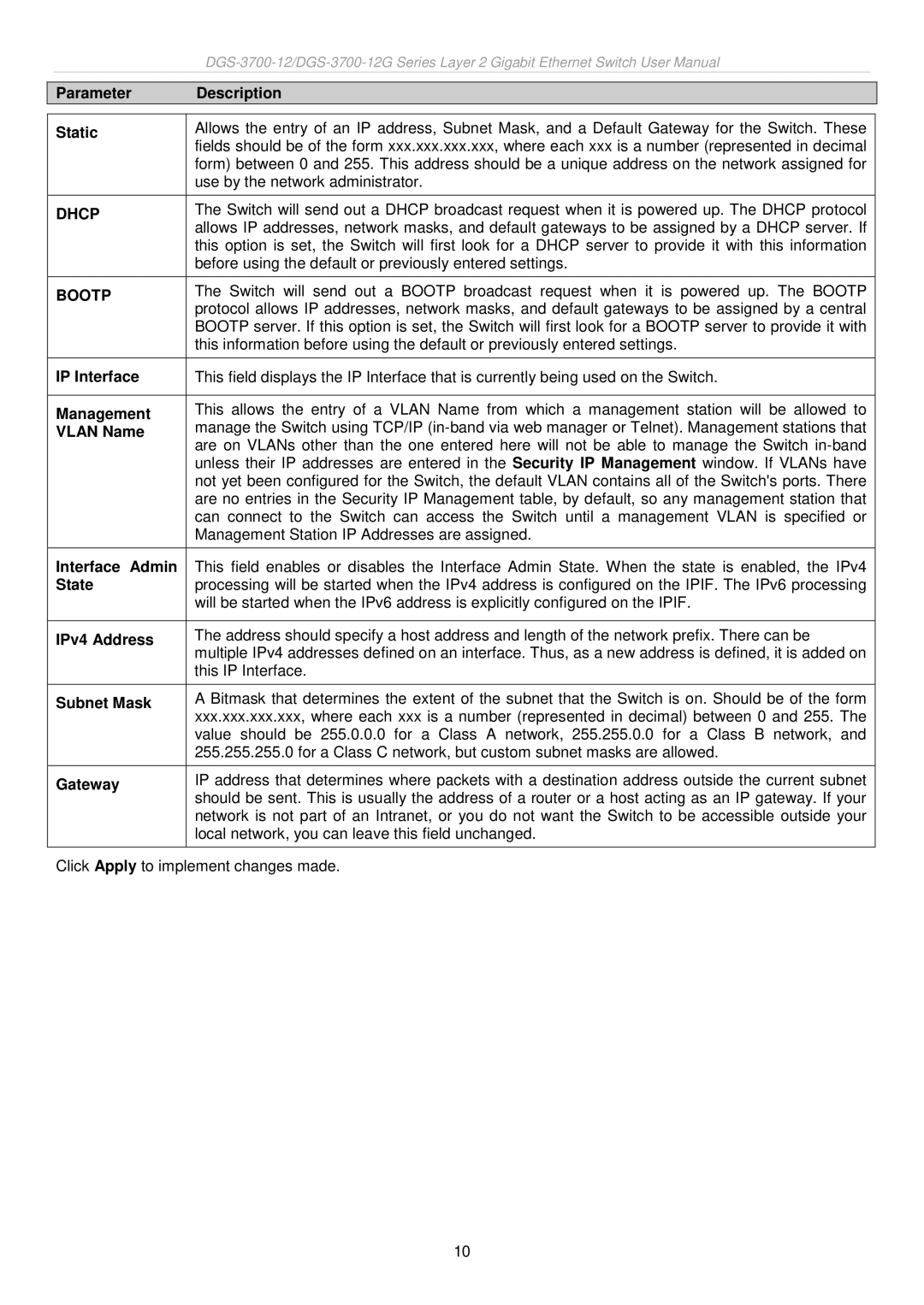
| Parameter | Description |
|
|
|
|
|
| Static | Allows the entry of an IP address, Subnet Mask, and a Default Gateway for the Switch. These |
|
|
| fields should be of the form xxx.xxx.xxx.xxx, where each xxx is a number (represented in decimal |
|
|
| form) between 0 and 255. This address should be a unique address on the network assigned for |
|
|
| use by the network administrator. |
|
| DHCP | The Switch will send out a DHCP broadcast request when it is powered up. The DHCP protocol |
|
|
| allows IP addresses, network masks, and default gateways to be assigned by a DHCP server. If |
|
|
| this option is set, the Switch will first look for a DHCP server to provide it with this information |
|
|
| before using the default or previously entered settings. |
|
| BOOTP | The Switch will send out a BOOTP broadcast request when it is powered up. The BOOTP |
|
|
| protocol allows IP addresses, network masks, and default gateways to be assigned by a central |
|
|
| BOOTP server. If this option is set, the Switch will first look for a BOOTP server to provide it with |
|
|
| this information before using the default or previously entered settings. |
|
| IP Interface | This field displays the IP Interface that is currently being used on the Switch. |
|
|
|
|
|
| Management | This allows the entry of a VLAN Name from which a management station will be allowed to |
|
| VLAN Name | manage the Switch using TCP/IP |
|
|
| are on VLANs other than the one entered here will not be able to manage the Switch |
|
|
| unless their IP addresses are entered in the Security IP Management window. If VLANs have |
|
|
| not yet been configured for the Switch, the default VLAN contains all of the Switch's ports. There |
|
|
| are no entries in the Security IP Management table, by default, so any management station that |
|
|
| can connect to the Switch can access the Switch until a management VLAN is specified or |
|
|
| Management Station IP Addresses are assigned. |
|
|
|
|
|
| Interface Admin | This field enables or disables the Interface Admin State. When the state is enabled, the IPv4 |
|
| State | processing will be started when the IPv4 address is configured on the IPIF. The IPv6 processing |
|
|
| will be started when the IPv6 address is explicitly configured on the IPIF. |
|
|
|
|
|
| IPv4 Address | The address should specify a host address and length of the network prefix. There can be |
|
|
| multiple IPv4 addresses defined on an interface. Thus, as a new address is defined, it is added on |
|
|
| this IP Interface. |
|
|
|
|
|
| Subnet Mask | A Bitmask that determines the extent of the subnet that the Switch is on. Should be of the form |
|
|
| xxx.xxx.xxx.xxx, where each xxx is a number (represented in decimal) between 0 and 255. The |
|
|
| value should be 255.0.0.0 for a Class A network, 255.255.0.0 for a Class B network, and |
|
|
| 255.255.255.0 for a Class C network, but custom subnet masks are allowed. |
|
|
|
|
|
| Gateway | IP address that determines where packets with a destination address outside the current subnet |
|
|
| should be sent. This is usually the address of a router or a host acting as an IP gateway. If your |
|
|
| network is not part of an Intranet, or you do not want the Switch to be accessible outside your |
|
|
| local network, you can leave this field unchanged. |
|
|
|
|
|
Click Apply to implement changes made.
10