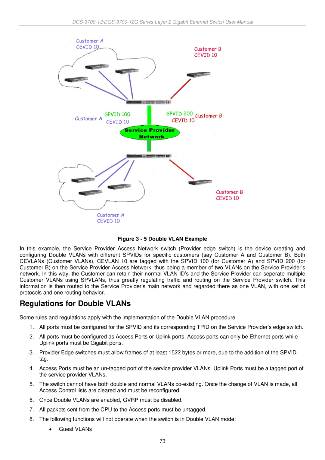
Figure 3 - 5 Double VLAN Example
In this example, the Service Provider Access Network switch (Provider edge switch) is the device creating and configuring Double VLANs with different SPVIDs for specific customers (say Customer A and Customer B). Both CEVLANs (Customer VLANs), CEVLAN 10 are tagged with the SPVID 100 (for Customer A) and SPVID 200 (for Customer B) on the Service Provider Access Network, thus being a member of two VLANs on the Service Provider’s network. In this way, the Customer can retain their normal VLAN ID’s and the Service Provider can seperate multiple Customer VLANs using SPVLANs, thus greatly regulating traffic and routing on the Service Provider switch. This information is then routed to the Service Provider’s main network and regarded there as one VLAN, with one set of protocols and one routing behavior.
Regulations for Double VLANs
Some rules and regulations apply with the implementation of the Double VLAN procedure.
1.All ports must be configured for the SPVID and its corresponding TPID on the Service Provider’s edge switch.
2.All ports must be configured as Access Ports or Uplink ports. Access ports can only be Ethernet ports while Uplink ports must be Gigabit ports.
3.Provider Edge switches must allow frames of at least 1522 bytes or more, due to the addition of the SPVID tag.
4.Access Ports must be an
5.The switch cannot have both double and normal VLANs
6.Once Double VLANs are enabled, GVRP must be disabled.
7.All packets sent from the CPU to the Access ports must be untagged.
8.The following functions will not operate when the switch is in Double VLAN mode:
•Guest VLANs
73