When PC B replies to the ARP request, its MAC address will be written into “Target H/W Address” in the ARP payload shown in
H/W | Protocol | H/W | Protocol | Operation | Sender | Sender | Target | Target |
type | type | address | address |
| H/W address | protocol | H/W address | protocol |
|
| length | length |
| address | address | ||
|
|
|
|
| ||||
|
|
|
|
|
|
|
|
|
|
|
|
| ARP reply | 10.10.10.1 | 10.10.10.2 | ||
|
|
|
|
|
|
|
|
|
Table – 3 (ARP Payload) |
|
|
|
|
|
| ||
When PC B replies the query, the “Destination Address” in the Ethernet frame will be changed to PC A’s MAC address. The “Source Address” will be changed to PC B’s MAC address (see
Destination address
Source address
Ether-type
ARP
FCS
Table – 4 (Ethernet frame format)
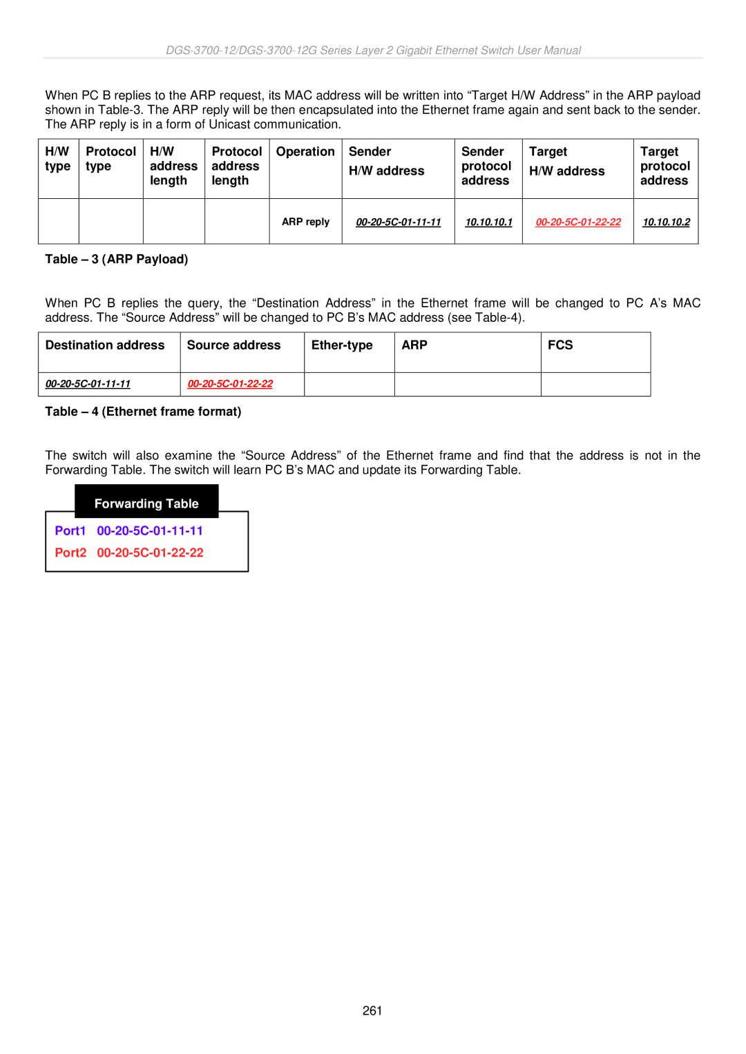
The switch will also examine the “Source Address” of the Ethernet frame and find that the address is not in the Forwarding Table. The switch will learn PC B’s MAC and update its Forwarding Table.
Forwarding Table
Port1 00-20-5C-01-11-11
Port2 00-20-5C-01-22-22
261