|
|
| ||
|
|
|
|
|
| Counter |
| Enable or disable the counter settings. |
|
|
|
|
|
|
| Ports |
| Specifies that the access rule will take effect on one port or a range of ports. |
|
|
|
|
|
|
| VLAN Name |
| Specifies the access rule will take effect on the VLAN Name specified. |
|
| VLAN ID |
| Specifies the access rule will take effect on the VLAN ID specified. |
|
Click Apply to display the following Access Rule List window.
Figure 6 - 26 Access Rule List (Packet Content)
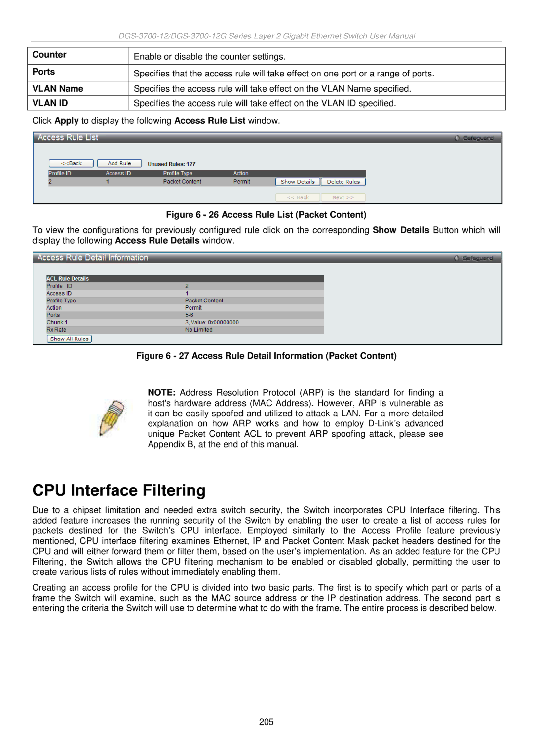
To view the configurations for previously configured rule click on the corresponding Show Details Button which will display the following Access Rule Details window.
Figure 6 - 27 Access Rule Detail Information (Packet Content)
NOTE: Address Resolution Protocol (ARP) is the standard for finding a host's hardware address (MAC Address). However, ARP is vulnerable as it can be easily spoofed and utilized to attack a LAN. For a more detailed explanation on how ARP works and how to employ
CPU Interface Filtering
Due to a chipset limitation and needed extra switch security, the Switch incorporates CPU Interface filtering. This added feature increases the running security of the Switch by enabling the user to create a list of access rules for packets destined for the Switch’s CPU interface. Employed similarly to the Access Profile feature previously mentioned, CPU interface filtering examines Ethernet, IP and Packet Content Mask packet headers destined for the CPU and will either forward them or filter them, based on the user’s implementation. As an added feature for the CPU Filtering, the Switch allows the CPU filtering mechanism to be enabled or disabled globally, permitting the user to create various lists of rules without immediately enabling them.
Creating an access profile for the CPU is divided into two basic parts. The first is to specify which part or parts of a frame the Switch will examine, such as the MAC source address or the IP destination address. The second part is entering the criteria the Switch will use to determine what to do with the frame. The entire process is described below.
205